RPLidar in ROS 2 Docker on Raspberry Pi
Introduction - RPLidar and ROS
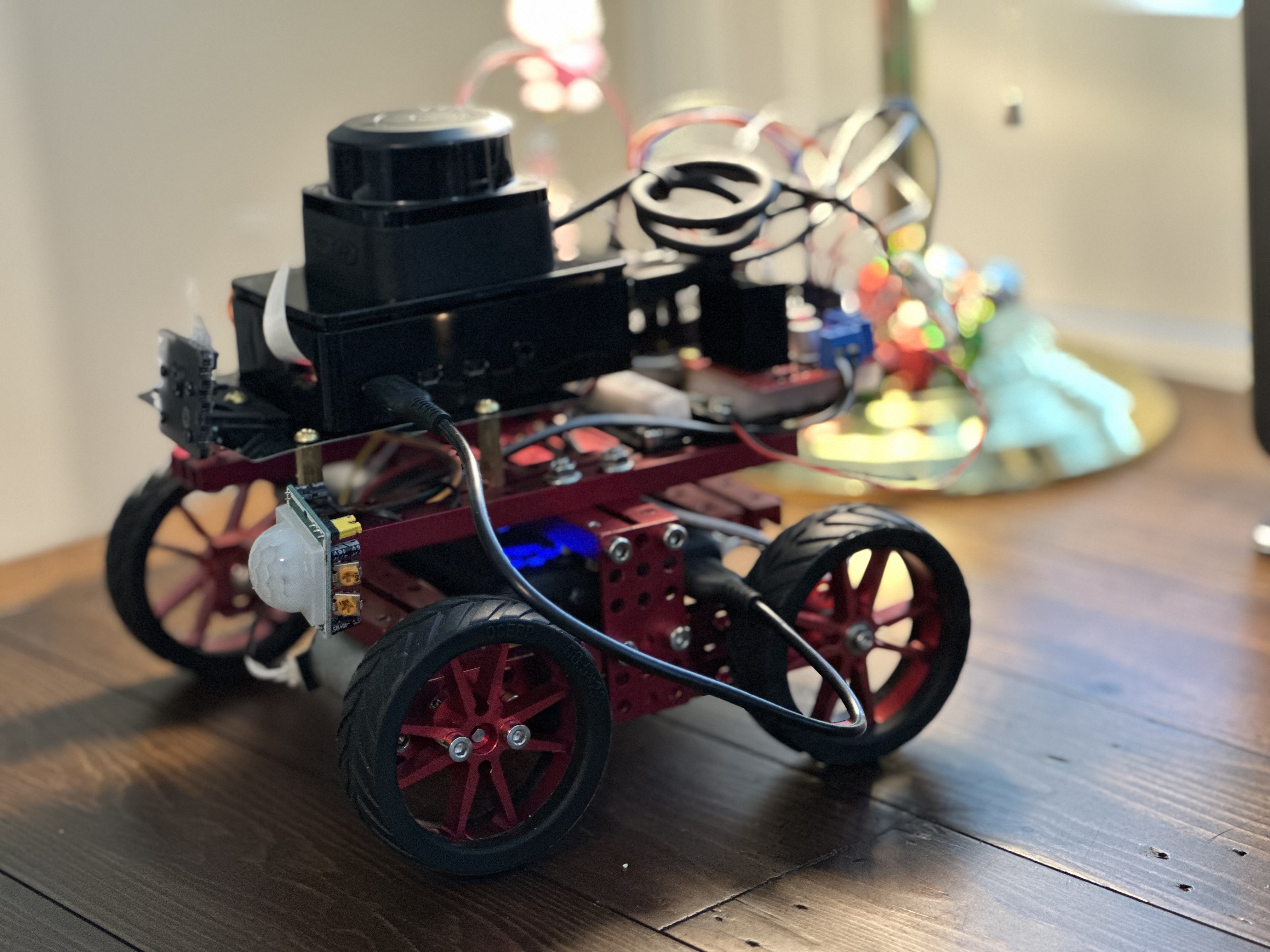
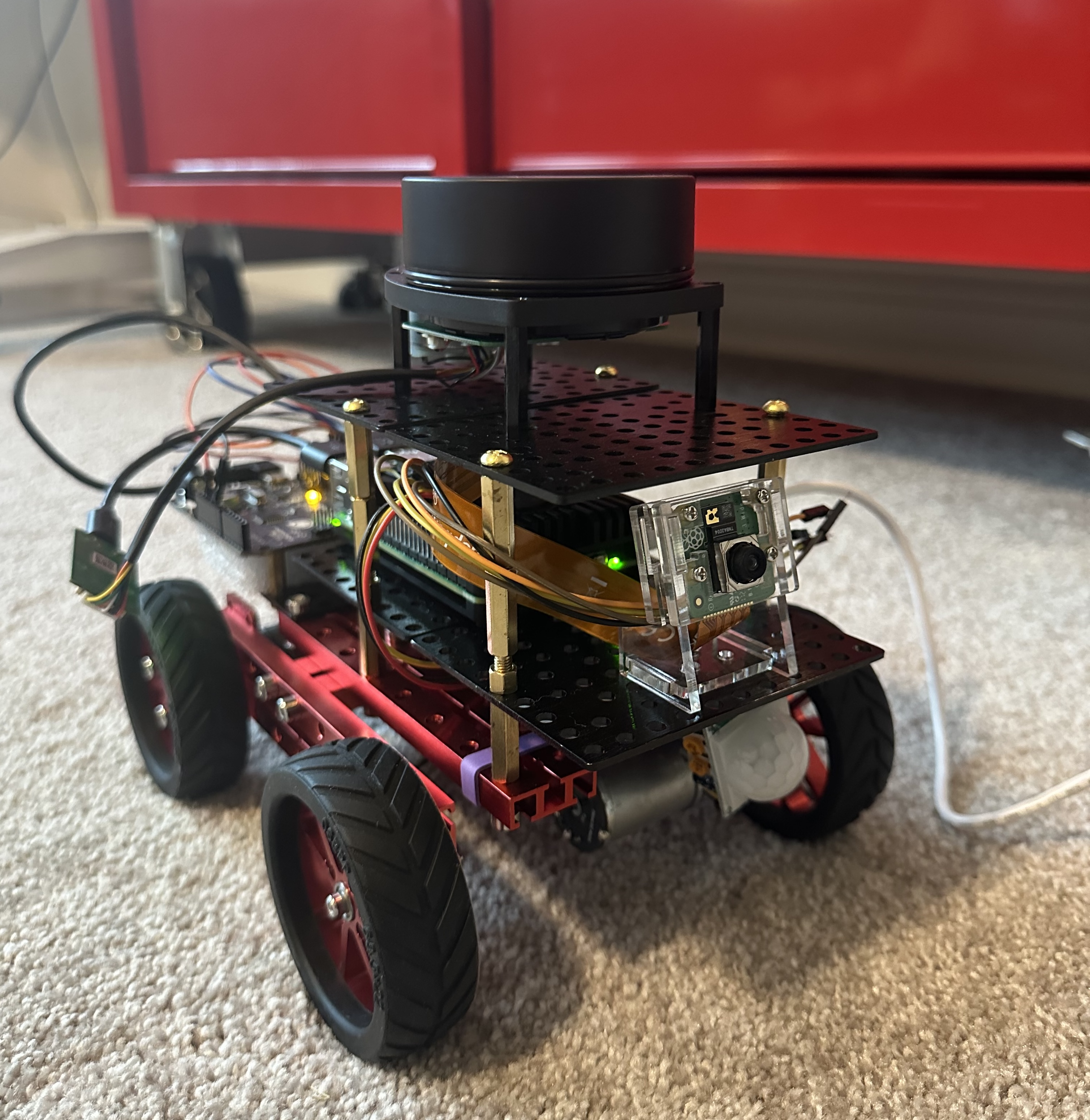
I purchased RPLidars for my security robot’s localization, mapping, and navigation. RPLidar is a 360-degree 2D LiDAR scanner that measures distances and detects obstacles using laser through triangulation or Time-of-Flight.
In Robotics, the Robot Operating System (ROS) is the default choice for building robot applications. It offers software libraries and tools that help developers seamlessly connect motors, sensors, and software and speed up the process of building advanced robots.
The RPLidar has a standard ROS node that reads data from an RPLidar 2D laser scanner and publishes that data as a message to a ROS topic. This allows other ROS nodes to access and utilize the laser scan information for tasks like obstacle avoidance or mapping in robotics applications. A ROS node is a program that runs on ROS and communicates with other nodes. Nodes are the basic building blocks of ROS and are used to perform computations and control systems.
The problem with using ROS on Raspberry Pi is that ROS only has “Tier 3” support on Raspbian, the OS optimized for the Raspberry Pi hardware. To use ROS on Raspberry Pi, we either install 64-bit Ubuntu or run ROS 2 Docker in the Raspberry Pi OS. I tried Ubuntu on Raspberry Pi and found it was too heavy for the little Pi. Therefore, I want to use ROS 2 Docker on Pi for my security robot. The concept of using Docker for robotic applications is relatively new.
By the way, ROS has two versions: ROS 1 and ROS 2. ROS 2 is the current version designed to be more flexible, secure, and performant than ROS 1.
Docker
Docker is widely used in enterprise software’s microservice architecture, where each service operates as a lightweight Docker container that can be independently deployed and upgraded. A Docker container can be created from a Docker image, which serves as a template defining its structure and dependencies.
The official ROS 2 Docker images are available here. There are several varieties: ros-core, ros-base, or perception, each one extending from the previous with additional ROS packages.
Dockerfile
To build robotic applications using ROS 2 Docker, we need to our own Dockerfile using the ROS 2 Docker image as the base image.
A Dockerfile is a text file containing instructions for creating a Docker image. It specifies the base image, adds dependencies, sets environment variables, and defines the application’s startup command. In our case, the base image will be the “ros:humble-perception” ROS 2 image.
Here is a starting Dockerfile I created for my security robot. This Dockerfile creates a “ros” user and a “ros” group, establishes a home directory, and configures the environment for the user. The environment variable “ROS_DOMAIN_ID” ensures that only systems in the same domain can communicate with one another.
Additionally, this Dockerfile creates a ROS workspace, “bot_ws”, which is necessary for developing ROS applications.
FROM ros:humble-perception

# Install essential utilities
RUN apt-get update && apt-get install -y \
    vim \
    python3-serial \
    && rm -rf /var/lib/apt/lists/*

# Create "ros" user and group
ARG USERNAME=ros
ARG USER_UID=1000
ARG USER_GID=${USER_UID}

ENV BOT_HOME=/home/${USERNAME}

RUN groupadd --gid ${USER_GID} ${USERNAME} \
  && useradd -s /bin/bash --uid ${USER_UID} --gid ${USER_GID} -m ${USERNAME} -d ${BOT_HOME} \
  && chown -R ${USER_UID}:${USER_GID} ${BOT_HOME}

USER ros

RUN echo "export ROS_DOMAIN_ID=1" >> ~/.bashrc \
  && echo "source /opt/ros/humble/setup.bash" >> ~/.bashrc

# Create the ROS 2 workspace
RUN mkdir -p ${BOT_HOME}/bot_ws/src

# Set default working directory
WORKDIR ${BOT_HOME}/bot_ws
Create a Docker image
Before building the Docker image with the Dockerfile above, we must install the Docker engine on the Raspberry Pi. Please follow the instructions on the official Docker website. Remember to configure the Docker engine to run as a non-root user, as it simplifies the Docker command.
Once the Docker engine is installed on the Pi, we can execute the command docker build -t my_bot_image . to create the Docker image.
Start the Docker container
To start the Docker container, use the docker run -it my_bot_image command.
Now that we have a container for robot development. Let’s see how to install the RPLidar there.
RPLidar
Technical Specification
I have two RPLidars, C1 and A1. Both are 360-degree 2D laser scanners. Let’s first look at the RPLidar C1, which has a diameter range of 0.05 meters to 12 meters, translating to approximately 2 inches to 39 feet in the scan range. This RPLidar has a scan rate of 10 Hz, which means 10 full circles per second, and a sample frequency of 5,000 samples per second.
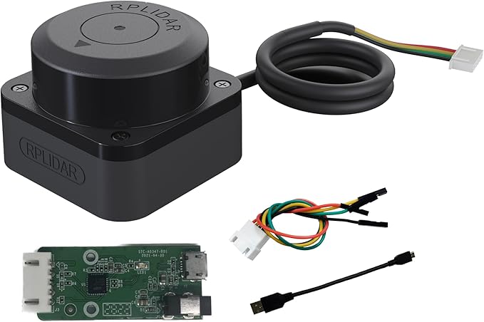
Here is the RPLidar A1, which has a scanning diameter range of 0.15 meters to 12 meters. Its scan rate is 5.5 Hz, and has a sample frequency of 8,000 samples per second.

The RPLidar C1 is a newer and more advanced model than the RPLidar A1. The C1 utilizes Direct Time-of-Flight (DTOF) technology, which allows for higher precision and improved performance. Additionally, the RPLidar C1 features a brushless motor that reduces mechanical friction and noise, enhancing its durability. The C1 is also significantly smaller and lighter than the A1, making it ideal for constructing home robots.
RPLidar driver code
To enable the RPLidar to scan and publish its scan data, we need its driver code. The RPLidar has a ROS2 git repository. We can clone and build that repository using colcon build. The RPLidar package provides a node that publishes the scan data to the ROS “/scan” topic, as well as ROS services to start and stop the RPLidar motor. Building from the ROS package source code is a common approach for utilizing third-party robotic hardware.
The RPLidar uses a serial port to communicate with ROS. The port must be specified when we start the RPLidar node. To find out which USB port is used by the RPLidar, let’s connect the lidar’s USB cable to the Pi and issue this command:
$ ls -l /dev/serial/by-id/
lrwxrwxrwx 1 root root 13 Feb 10 17:25 usb-Silicon_Labs_CP2102_USB_to_UART_Bridge_Controller_0001-if00-port0 -> ../../ttyUSB0
$ ls -l /dev/ttyUSB*
crw-rw---- 1 root dialout 188, 0 Feb 10 17:47 /dev/ttyUSB0
The command output tells us a few things:
- “/dev/ttyUSB0” is used by the RPLidar as the serial port;
- The root user and the “dialout” group have read-write permission on the port.
- The device’s major number is 188, which stands for “USB serial” in the linux manual
Run RPLidar in ROS 2 Docker
Update my_bot Docker Image
With all this information, we are ready to update our Docker images for running RPLidar in Docker:
First, we must add a line to the Dockerfile granting the “ros” user permission to access the ttyUSB port.
# add the user to the dialout group
RUN usermod -a -G dialout ${USERNAME}
Next, we add the following lines to download and build the RPLidar nodes:
# download the rplidar source code
RUN cd ${BOT_HOME}/bot_ws/src \
  && git clone -b ros2 https://github.com/Slamtec/rplidar_ros.git

# Source ROS 2 env and build the rplidar nodes
RUN /bin/bash -c "source /opt/ros/humble/setup.bash && \
    cd ${BOT_HOME}/bot_ws && \
    colcon build --symlink-install --packages-select rplidar_ros"
Click here to download the updated Dockerfile.
Now, let’s rebuild the Docker image using the updated Dockerfile:
docker build -t my_bot_image .
Create my_bot Docker Container
To let a Docker container use a device connected to the host machine, we need to specify which device port the container requires. In the case of RPLidar, we must specify the ttyUSB port when starting the container.
A straightforward approach is to use the docker run --device option, as follows: docker run -it --network=host --ipc=host --device=/dev/ttyUSB0 my_bot_image. However, over time, I found this is not the most convenient way, as the USB port can change after reconnecting the RPLidar’s USB cable. Therefore, a better method is to map to all devices and then use device group rules to restrict it to only USB serial converters belonging to device group 188, as mentioned in the previous section.
docker run -it --rm --network=host --ipc=host -v /dev:/dev \
    --device-cgroup-rule='c 188:* rmw' \
    --device-cgroup-rule='c 166:* rmw' \
    my_bot_image
Once in the Docker container, we run the RPLidar ROS 2 launch file. We then list the nodes, topics, and services to verify the RPLidar runs correctly.
# start rplidar_c1
$ ros2 launch rplidar_ros rplidar_c1_launch.py serial_port:=/dev/ttyUSB0

$ ros2 node list
/rplidar_node

$ ros2 topic list
/parameter_events
/rosout
/scan

$ ros2 service list
/rplidar_node/describe_parameters
/rplidar_node/get_parameter_types
/rplidar_node/get_parameters
/rplidar_node/list_parameters
/rplidar_node/set_parameters
/rplidar_node/set_parameters_atomically
/start_motor
/stop_motor
The command to start the RPLidar A1 is similar; simply replace “c1” in the launch file with “a1”:
$ ros2 launch rplidar_ros rplidar_a1_launch.py serial_port:=/dev/ttyUSB0
If you receive the error code “80008004” from ros2 launch rplidar_ros, it indicates a communication issue between the ROS node and the RPLidar hardware. Please verify if the OS recognizes the LiDAR device at the specified ttyUSB.
$ ls -l /dev/serial/by-id/
$ ls -l /dev/ttyUSB*
We can stop the RPLidar motor to conserve the energy used by the robot. Here are commands to stop and start the RPLidar motor.
# stop the RPLidar motor
$ ros2 service call /stop_motor std_srvs/srv/Empty

# start the RPLidar motor
$ ros2 service call /start_motor std_srvs/srv/Empty
Viewing the Lidar Scan
The ROS on Raspberry Pi acts as the robot controller. To keep it lightweight, it only has a command interface. To monitor the robot’s activities, I use a separate system, typically an Ubuntu Linux desktop, which has a graphical user interface and subscribes to the topics published by the robot from the Pi.
The ROS desktop version includes RViz, a 3D visualization tool for displaying sensor data and the environments in which robots operate. It helps developers and operators observe how robots interact with their surroundings in real-time or through recorded data. RViz uses a plugin architecture that enables the addition of custom visualizations or data displays, making it highly extensible.
As mentioned earlier, we set the environment variable “export ROS_DOMAIN_ID=1” to control who can access the data published by the robot running on Raspberry Pi. I installed the ROS 2 Desktop version on my Ubuntu Linux machine. Detailed installation steps can be found here.
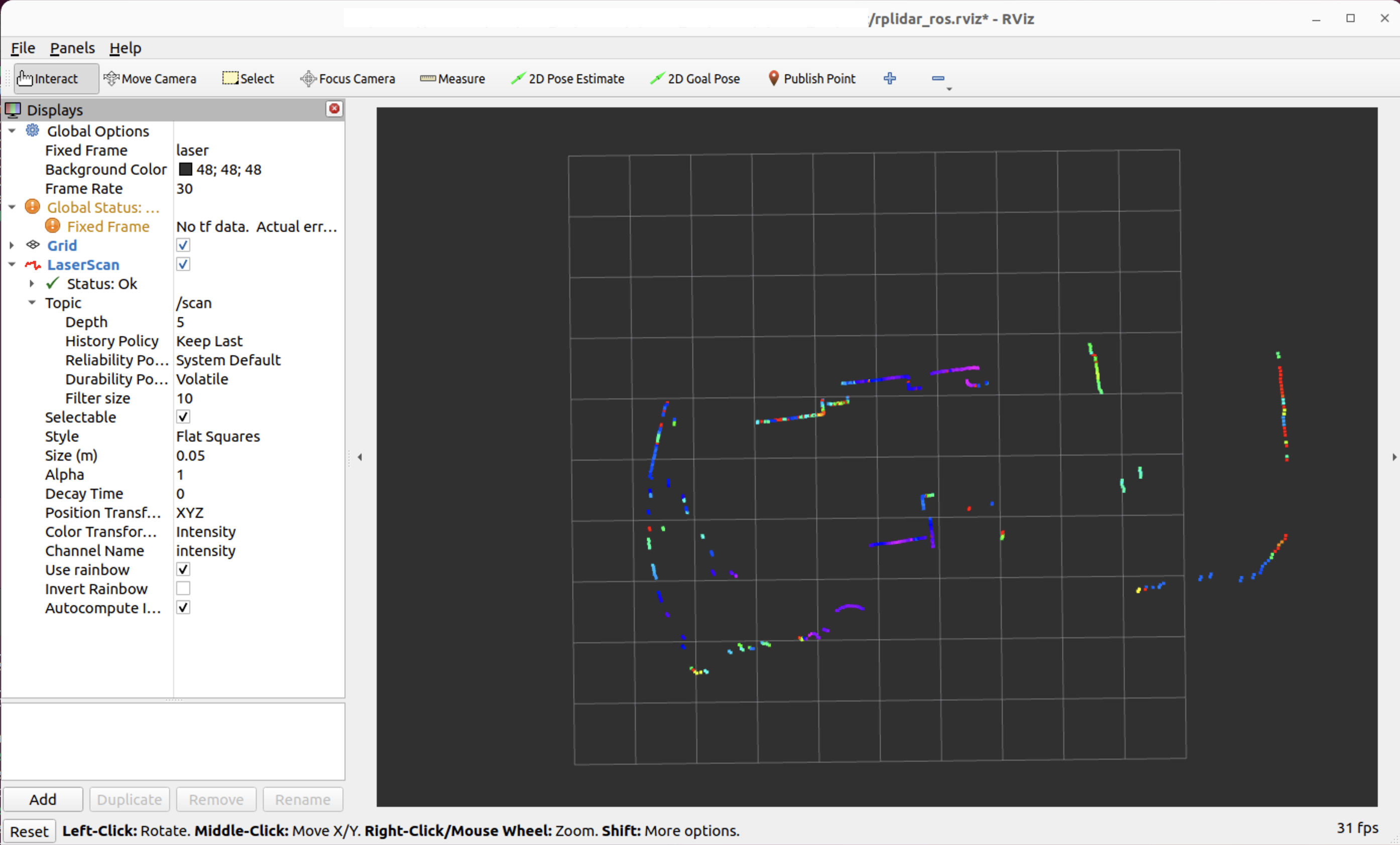
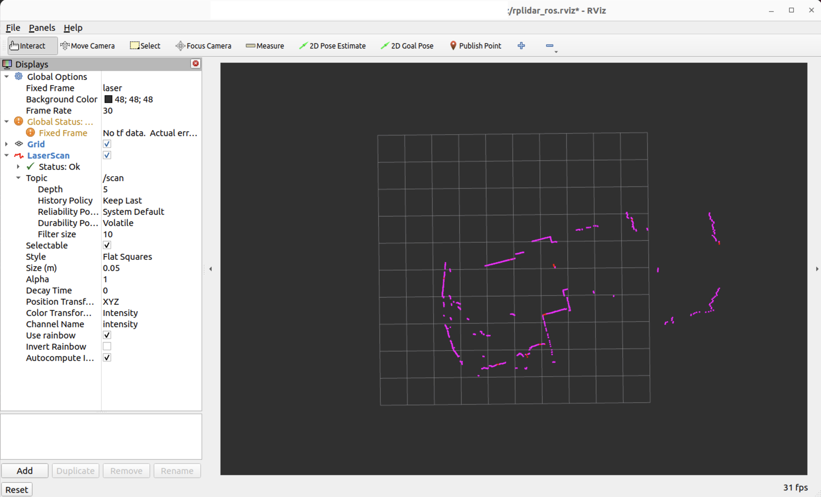
Viewing the scan data in RViz isn’t the easiest task. We need to add the “LaserScan” with the “/scan” topic and some configurations. To simplify this process, I created a launch file in the rplidar_ros package. Instead of configuring RViz manually, type the command ros2 launch rplidar_ros view_rviz2.py in the linux desktop after rebuilding the rplidar_ros package.
$ ros2 launch rplidar_ros view_rviz2.py
Here, by using RViz, I can view the robot’s lidar scan from my Ubuntu desktop. On the left side is the curved bay window of my office. A desk, a bookshelf, and a cat tower sit next to the window, making that area quite busy.
Scan from the RPLidar C1:
Scan from the RPLidar A1:
Cheers!