ROS 2 Control, Robot Control the Right Way
My journey of building a mobile robot using ROS2 and ros2_control.
First Attempt - Raspberry Pi GPIO
When I began building mobile robots with ROS, I was unaware of ros2_control. I used ROS nodes to communicate directly with the Raspberry Pi’s GPIO pins, controlling the sensors and motors. A ROS node is a program that runs on ROS and interacts with other nodes. Nodes are the basic building blocks of ROS and are used to perform computations and control systems.
ROS Node Graph
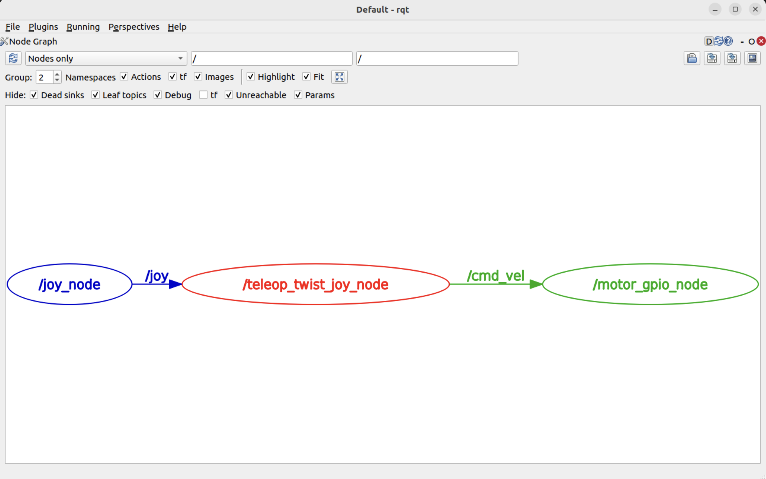
In the initial version of the robot, my PS5 gamepad utilizes the joystick’s “joy_node” to publish velocity and direction messages to the “/cmd_vel” topic. My “motor_gpio_node” consumes these messages and directs the GPIO pin’s Pulse Width Modulation (PWM) signals to the wheel motor.
Here is the “Node Graph” introspection from ROS RQT. RQT is a collection of plugins that offers a graphical user interface for ROS, enabling developers to visualize and interact with the robot’s internals.
Direct RPI.GPIO Communication
Watching the robot come to life and respond to my gamepad’s joystick was quite enjoyable. Here is the “motor_gpio_node” code written in Python:
class MotorSubscriber(Node):

    def listener_callback(self, msg):
        # extract linear and angular velocities from Twist message
        linear_vel = msg.linear.x
        angular_vel = msg.angular.z

        # 1. set motor direction on digital pins
        GPIO.output(RIGHT_MOTOR_1, linear_vel > 0)
        GPIO.output(RIGHT_MOTOR_2, linear_vel < 0)
        GPIO.output(LEFT_MOTOR_1, linear_vel > 0)
        GPIO.output(LEFT_MOTOR_2, linear_vel < 0)

        # 2. set speed using PWM. The angular velocity will "weigh" the motors speed.
        # map from the cmd_vel linear range to the motor's PWM range
        motor_speed = self.map(abs(linear_vel), LINEAR_X_MIN, LINEAR_X_MAX, PWM_MIN, PWM_MAX)
        right_pwm = self.compute_pwm(motor_speed, angular_vel)
        left_pwm = self.compute_pwm(motor_speed, angular_vel)

        self.pwm_right.ChangeDutyCycle(right_pwm)
        self.pwm_left.ChangeDutyCycle(left_pwm)
After the excitement faded, I felt I was overloading the Raspberry Pi. The Pi should concentrate on robot control and high-level processing while delegating hardware communication to another device. This is where Arduino comes into the picture.
Second Attempt - Raspberry Pi with Arduino
Arduino is a microcontroller optimized for low-level tasks, such as precise PWM motor control, reading motor encoder outputs, retrieving sensor data, and managing real-time tasks without the overhead of an operating system. In contrast, Raspberry Pi is a single-board computer that can run AI models and execute path-planning algorithms.
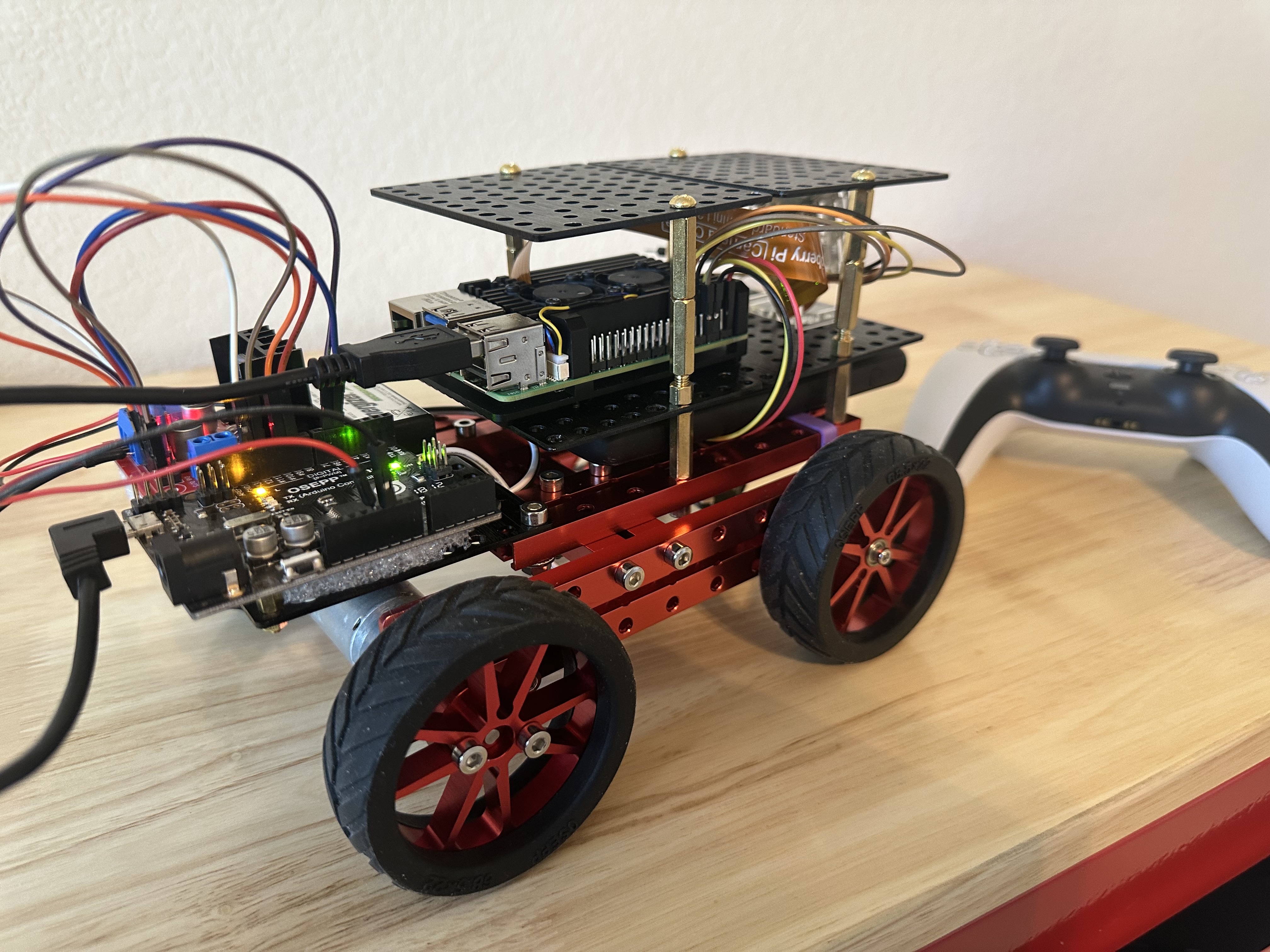
I integrated Arduino into my robot design and rewired the motors, LED light, and PIR sensor. Here is its current appearance.
Coding for the Arduino Board
Writing code for Arduino differs significantly from high-level programming languages due to its emphasis on hardware interaction, real-time processing, and resource limitations. Here’s what makes it unique:
- Arduino executes bare-metal code without an operating system. Arduino code interacts directly with hardware through digital and analog pins.
- Code is written in the Arduino IDE and saved as Sketches. Each Sketch contains two primary functions; everything operates sequentially within the loop() function.
void setup() {
    // Runs once at startup
}

void loop() {
    // Runs repeatedly
}
Due to its unique interaction style, Arduino can execute tasks with precision and in real-time.
Serial Port Communication
Raspberry Pi communicates with Arduino using either a Serial port or I2C. The serial port is simpler and has default support. I2C allows for multiple boards but requires slightly more complex wiring. A serial connection can be established through UART or USB. For quick prototyping, I used Serial over USB. After connecting the Raspberry Pi to Arduino, I could find the serial port on the Pi using this command:
$ ls -l /dev/serial/by-id
lrwxrwxrwx 1 root root 13 Feb 20 17:05 usb-Arduino__www.arduino.cc__0043_956353339303515160E1-if00 -> ../../ttyACM0
I tested the serial communication on the Raspberry Pi using the Python utility called “mini-term,” as shown below.
$ python3 -m serial.tools.miniterm -e /dev/ttyACM0 57600
--- Miniterm on /dev/ttyACM0  57600,8,N,1 ---
--- Quit: Ctrl+] | Menu: Ctrl+T | Help: Ctrl+T followed by Ctrl+H ---
r
OK
- “/dev/ttyACM0” is the serial port identified from the above “by-id” command,
- “57600” is the “baudrate”, declared in the Arduino sketch setup function.
- The output from the miniterm depends on the Arduino code in the loop function.
The baud rate is the communication speed between two devices over a serial port, representing the number of bits transmitted per second (bps). The default setting is 9600. The output of the mini-term depends on what is loaded onto the Arduino board.
Firmata
At this stage, my robot is quite simple. The control node calculates the PWM value and sends it to the Arduino to control the direction and velocity of the wheels. Therefore, I can use the standard Firmata instead of writing my own delegate code for Arduino. Firmata comes with the Arduino IDE and can be accessed through File -> Examples -> Firmata -> StandardFirmata. Once the Firmata sketch is uploaded to the Arduino board, the Arduino side is ready to receive commands from the Raspberry Pi.
Here’s what to configure on the Raspberry Pi:
- Install pyFirmata -
pip3 install pyfirmata - Grant the robot user permission to read and write the serial port -
sudo adduser $USER dialout - Update the ROS node to use pyFirmata
import pyfirmata

board = pyfirmata.Arduino('/dev/ttyACM0')

board.digital[RIGHT_MOTOR_1].write(0)
board.digital[RIGHT_MOTOR_2].write(0)
...
Firmata works well for a simple robot, but I must explore more sophisticated options as my robot advances.
Third Attempt - ros2_control
The mobile robot I want to build will drive itself using a map, localization, and navigation. A motor encoder is needed to tell its velocity and position, and the robot will efficiently control the motor using the PID algorithm. Therefore, a simple open loop and pass-through control is not enough. I need a feedback loop and real-time, low-latency execution using ros2_control.
What is ros2_control
ros2_control is a robot control framework in ROS 2 that provides a hardware abstraction layer for controlling robot actuators, sensors, and hardware interfaces in a modular and efficient way.
The primary benefit of ros2_control is that it enhances performance and offers real-time capabilities. The ros2_control conducts a direct, low-latency interface with the hardware by reducing ROS message overhead when communicating with actuators and sensors. The ROS 2 controllers operate within a single process rather than multiple processes collaborating through messages and topics.
In addition to performance and efficiency advantages, ros2_control also promotes standardization and modular robot control. It supports various hardware interfaces through the hardware abstraction layer and enables a seamless transition between simulated and different hardware implementations with little code change. Developers can reuse existing controllers instead of writing their own from scratch. In fact, much of the robot control logic has already been developed by others, so the pre-built ROS2 controllers can be utilized as is in most use cases.
For reference, ros2_control supports various types of control for the wheeled mobile robot.
Update My Code to Use ros2_control
To incorporate ros2_control into my robot, here are the changes I made:
- Update the robot launch file to use standard ROS2 controllers.
- Add two new configuration files.
- Add the hardware plugin that communicates with the Arduino for the state and command of the motors.
- Create an Arduino sketch that provides encoder readings, open-loop and closed-loop control.
- Remove my RO2 node “motor_gpio_node”.
Here are more details about each change. The hardware plugin and Arduino sketch (items #3 and #4) are downloaded from the robotics community.
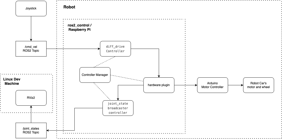
ROS 2 Launch File
This is the robot’s launch file that uses the standard ros2_controllers. They are controllers for the Differential Drive and the Joint State Broadcaster.
def generate_launch_description():
...
    control_node = Node(
        package="controller_manager",
        executable="ros2_control_node",
        parameters=[robot_controllers],
        output="both",
        remappings=[
            ("~/robot_description", "/robot_description"),
            ("/diffbot_base_controller/cmd_vel", "/cmd_vel"),
        ],
    )

    robot_state_pub_node = Node(
        package="robot_state_publisher",
        executable="robot_state_publisher",
        output="both",
        parameters=[robot_description],
    )

    joint_state_broadcaster_spawner = Node(
        package="controller_manager",
        executable="spawner",
        arguments=["joint_state_broadcaster", "--controller-manager", "/controller_manager"],
    )

    robot_controller_spawner = Node(
        package="controller_manager",
        executable="spawner",
        arguments=["diffbot_base_controller", "--controller-manager", "/controller_manager"],
    )

    # Delay start of joint_state_broadcaster after `robot_controller`
    delay_joint_state_broadcaster_after_robot_controller_spawner = RegisterEventHandler(
        event_handler=OnProcessExit(
            target_action=robot_controller_spawner,
            on_exit=[joint_state_broadcaster_spawner],
        )
    )

    nodes = [
        control_node,
        robot_state_pub_node,
        robot_controller_spawner,
        delay_joint_state_broadcaster_after_robot_controller_spawner,
    ]

    return LaunchDescription(declared_arguments + nodes)
New Configuration Files
The “ros2_control.xacro” describes the hardware plugin.
<?xml version="1.0"?>
<robot xmlns:xacro="http://www.ros.org/wiki/xacro">
    <ros2_control name="RealRobot" type="system">
        <hardware>
            <plugin>diffdrive_arduino/DiffDriveArduinoHardware</plugin>
            <param name="left_wheel_name">left_wheel_joint</param>
            <param name="right_wheel_name">right_wheel_joint</param>
            <param name="loop_rate">30</param>
            <param name="device">/dev/ttyACM0</param>
            <param name="baud_rate">57600</param>
            <param name="timeout_ms">1000</param>
            <param name="enc_counts_per_rev">2000</param>
        </hardware>
        <joint name="left_wheel_joint">
            <command_interface name="velocity">
                <param name="min">-10</param>
                <param name="max">10</param>
            </command_interface>
            <state_interface name="position"/>
            <state_interface name="velocity"/>
        </joint>
        <joint name="right_wheel_joint">
            <command_interface name="velocity">
                <param name="min">-10</param>
                <param name="max">10</param>
            </command_interface>
            <state_interface name="position"/>
            <state_interface name="velocity"/>
        </joint>
    </ros2_control>
</robot>
The “diffbot_controllers.yaml” file is used to tweak the controller behaviors.
controller_manager:
  ros__parameters:
    update_rate: 10  # Hz

    joint_state_broadcaster:
      type: joint_state_broadcaster/JointStateBroadcaster

    diffbot_base_controller:
      type: diff_drive_controller/DiffDriveController

diffbot_base_controller:
  ros__parameters:
    publish_rate: 50.0

    base_frame_id: base_link

    left_wheel_names: ["left_wheel_joint"]
    right_wheel_names: ["right_wheel_joint"]
    wheel_separation: 0.14
    wheel_radius: 0.03
    ...
Hardware Plugin and Arduino sketch
The hardware plugin “diffdrive_arduino/DiffDriveArduinoHardware” I used was originally developed by the robotics community. I made some adjustments for my motors and easier wiring. I clone the git repository and built it using colcon in my ROS 2 workspace.
The Arduino sketch works with the hardware plugin and can be downloaded here.
Let the Robot Dance
I want to see how well the robot reacts to the joystick’s twists and turns, so I created this robot dance clip. Cheers! :D
# start the robot on Raspberry Pi
ros2 launch my_bot robot.launch.py

# start the joystick teleop on the linux dev machine
ros2 launch teleop_twist_joy teleop-launch.py joy_config:='ps3'