ROS2 Control of the LEGO Audi e-tron
My journey of building a mobile robot using ROS2 and ros2_control.
Introduction
After building a differential robot (Robot Auto Mapping using Nav2 SLAM Toolbox) using mechanical parts from OSEPP, I am looking to build a more durable mobile robot with stronger motors and a more attractive look.
I started with RC cars. However, to modify an RC car for ROS2 Control, I would have to discard many of its original RC parts, which is not very economical. Besides, the modified RC car does not look good.
I grew up as a LEGO fan and am now an AFOL (Adult Fan of LEGO). LEGO is the ultimate building block. I can take the blocks and build anything I want. Thanks to LEGO® Technic™, which releases model rally cars with real motors and hubs.
LEGO® Technic™ 42160
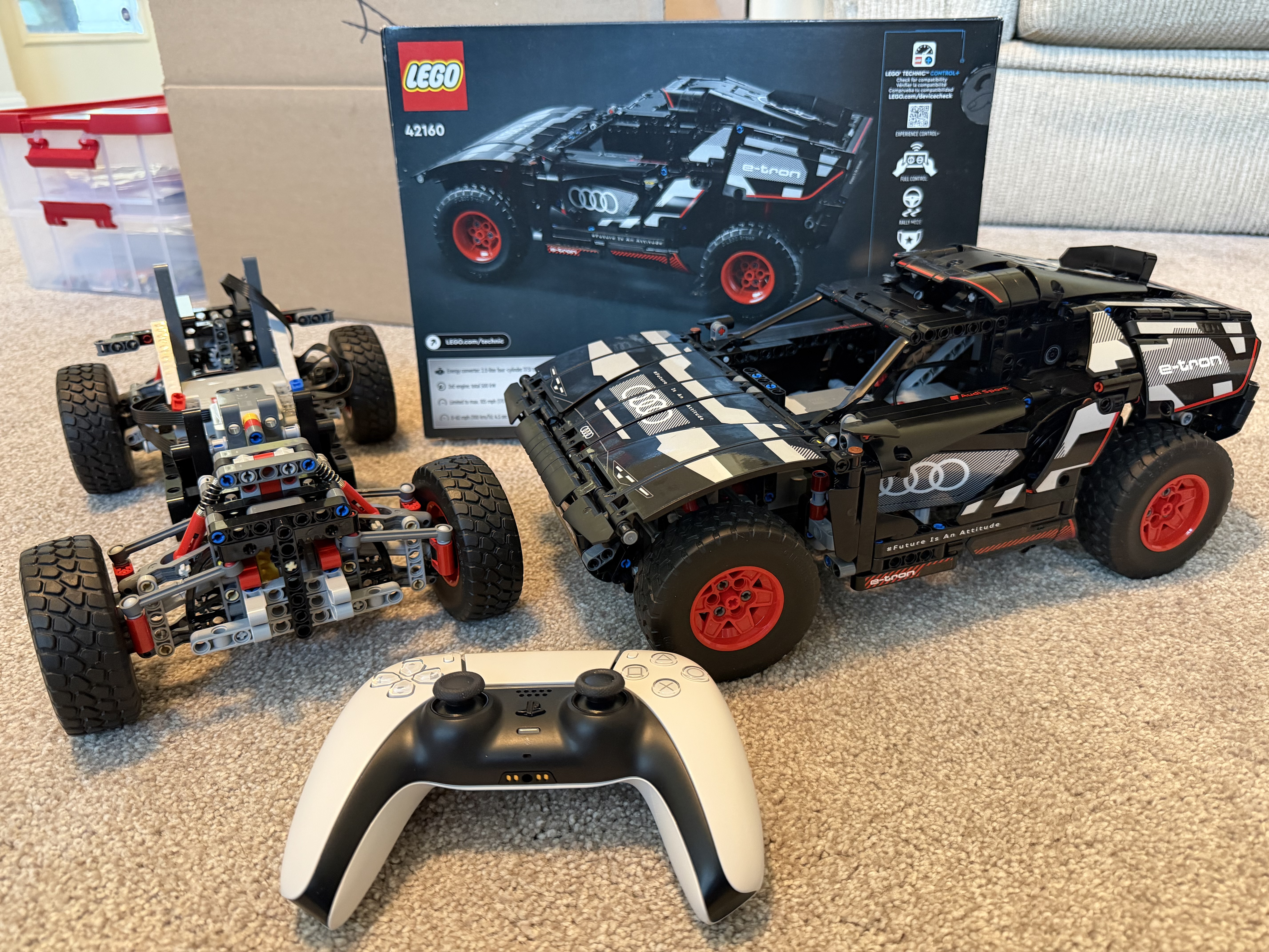
The LEGO Audi RS Q e-tron (Technic™ 42160) is a model of the 2022 Audi RS Q e-tron Dakar rally car. It features many realistic details, including individual suspension on each of the car’s 4 wheels and wheel elements that reflect the full-sized Audi’s wheel design.
Like a real-world rally car, the LEGO Audi e-tron has front-wheel steering and all-wheel drive. The model car is powered by three Technic™ motors, connected to the ports of the Technic™ Hub.
The LEGO Audi e-tron can be controlled via LEGO’s Control+ iOS and Android apps, but I want to control it with ROS2 and ROS2 Control so it can integrate with the larger ecosystem and do more than just drive. :)
ROS2 Controlled LEGO Car
What and Why ROS2 Control
ros2_control is a robot control framework in ROS 2 that provides a hardware abstraction layer for controlling robot actuators, sensors, and hardware interfaces in a modular and efficient way.
ros2_control enhances performance and offers real-time capabilities by avoiding multiple processes that collaborate via messages and topics. Besides, it promotes standardization and modular robot control. It supports various hardware interfaces through a hardware abstraction layer and enables a seamless transition between simulation and different hardware implementations with minimal code changes.
Developers can reuse existing controllers instead of writing their own from scratch. In fact, much of the robot control logic has already been developed by others, so the pre-built ROS2 controllers can be utilized as is in most use cases.
ROS2 Controllers for Wheeled Mobile Robots
For wheeled mobile robots, ros2_control framework offers the following types of controllers.
- Differential Drive Controller:
- Controller for mobile robots with differential drive, which has two wheels, each of which is driven independently.
- Steering Controllers:
- Bicycle - with the front wheel(s) steerable and the traction wheel(s) at the rear.
- Tricycle - with a steerable front wheel and two independent traction wheels at the rear.
- Ackermann - with two independent steering wheels at the front and two independent traction wheels at the rear.
- Mecanum Drive Controllers:
- Controller for a mobile robot with four mecanum wheels, allowing the robot to move sideways, spin, and drive in any direction by controlling each wheel independently.
For more information about the ROS2 Steering Controller, please see the documentation on control.ros.org and steering_controllers. The second article provides detailed information on the controller’s command and state interfaces, parameters, and subscribed and published topics.
Bicycle Steering Controllers for LEGO Audi e-tron
This LEGO Audi e-tron is a car-like robot. It has steerable front wheels and all-wheel drive. The two front wheels work together to steer the car, and all wheels provide the same traction and forward and backward motion to propel it.
This resembles the Bicycle Steering model. Therefore, a bicycle steering controller is used for this LEGO car, utilizing two joints, virtual_rear_wheel_joint and virtual_front_wheel_joint, to control its movement.
Architecture
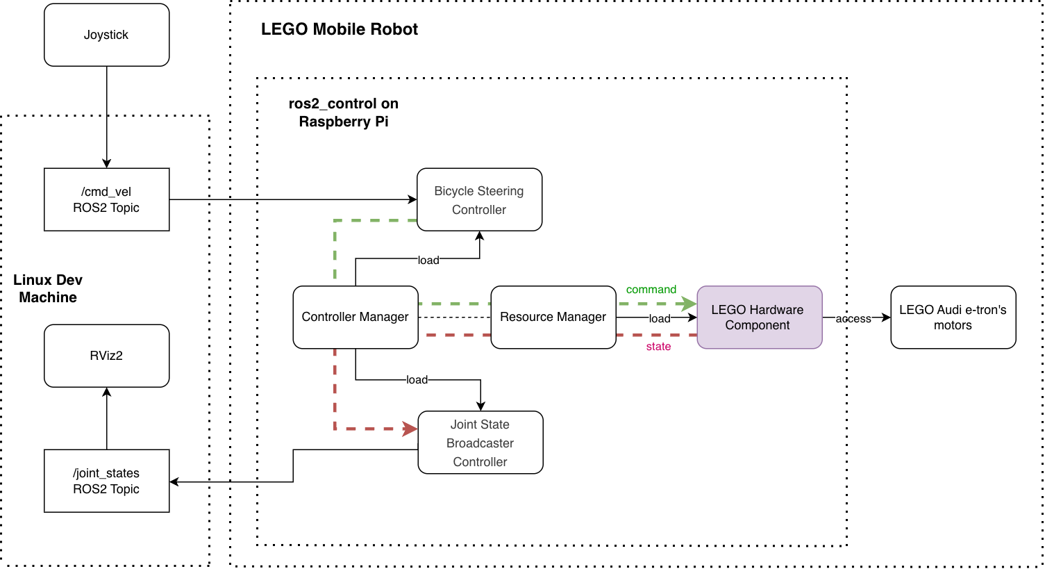
Here is the architecture diagram for a ROS2-controlled LEGO car, where the Controller Manager connects the controllers and the hardware abstraction of the ros2_control framework. On the one hand, the Controller Manager manages controllers (e.g., loading, activating, deactivating, and unloading them). On the other hand, it accesses the hardware components via the Resource Manager.
The control loop is managed by the Controller Manager’s update() method. It reads data from the hardware components, updates the outputs of all active controllers, and writes the results back to the components.
The Resource Manager loads the hardware component, manages its lifecycle, and exposes its command and state interfaces. During control loop execution, the Resource Manager’s read() and write() methods communicate with the hardware component.
To support the LEGO car, we need to implement the LEGO hardware component, which is the driver program for the physical LEGO car. The remaining components in the diagram are provided by the ros2_control framework.
ros2_control LEGO Hardware Component
There are three basic types of hardware components:
- Actuator: Simple 1-DOF (Degrees of Freedom) robotic hardware, such as motors and valves. An actuator implementation is related to only one joint.
- System: Multi-DOF robotic hardware such as industrial robots. This component has reading and writing capabilities and can have multiple joints.
- Sensor: Robotic hardware used for sensing its environment.
I use the “System” type for the LEGO hardware component because it has 2-DOF and uses two joints, virtual_rear_wheel_joint and virtual_front_wheel_joint, for steering and traction.
Hardware Description in URDF
The ros2_control framework uses the <ros2_control> tag in the robot’s URDF file to describe the components and the hardware setup. Here is my ros2_control.xacro:
<?xml version="1.0"?>
<robot xmlns:xacro="http://www.ros.org/wiki/xacro">
  <xacro:macro name="carlikebot_ros2_control" params="name prefix">

    <ros2_control name="${name}" type="system">
      <hardware>
        <plugin>audi_etron/CarlikeBotSystemHardware</plugin>
        <!-- LEGO Motor Control Parameters -->
        <!-- Maximum power for traction motors (0-100), default 80  -->
        <param name="max_traction_power">90.0</param>
        <!-- Maximum power for traction motors (0-100), default 50  -->
        <param name="max_steering_power">50.0</param>
        <!-- Maximum velocity command for scaling (rad/s) -->
        <param name="max_traction_velocity">25.0</param>
        <!-- Maximum steering position for scaling (rad), default 0.4 (~22.9 degrees)
             Must match URDF joint limits. Turning radius at max ~0.57m (wheelbase 0.24m) -->
        <param name="max_steering_position">0.4</param>
        <param name="steering_deadzone">0.05</param>
        <!-- Hub name pattern to search for during BLE scan, default "Technic" -->
        <param name="hub_name">Technic</param>
      </hardware>
      <joint name="${prefix}virtual_front_wheel_joint">
        <command_interface name="position"/>
        <state_interface name="position"/>
      </joint>
      <joint name="${prefix}virtual_rear_wheel_joint">
        <command_interface name="velocity"/>
        <state_interface name="velocity"/>
        <state_interface name="position"/>
      </joint>
    </ros2_control>

  </xacro:macro>
</robot>
Among the LEGO Motor Control parameters, the max_steering_power limits the power sent to the steering motor. It defaults to 50% for the following reasons:
- Steering requires smooth, precise control, and lower power reduces jerky movements.
- Lower steering power provides mechanical protection because steering components are typically more delicate; limiting power reduces stress.
- Steering only turns the front wheels, which requires less torque than driving the car.
Hardware Component Class
The hardware component is a ROS2 package written in C++ with ament_cmake as the build type. A helpful command for creating the package is ros2 pkg create. After creating the package, add
The hardware_interface class must implement LifecycleNodeInterface’s on_configure, on_cleanup, on_shutdown, on_activate, on_deactivate, on_error methods; and overriding SystemInterface’s on_init, export_state_interfaces, export_command_interfaces, read, write.
For my LEGO CarlikeBotSystemHardware class, the LEGO motor’s control parameters are initialized in the on_init method. The on_activate method connects to the LEGO Technic Hub, and the on_deactivate method disconnects.
Code snippet from carlikebot_system.cpp:
hardware_interface::CallbackReturn CarlikeBotSystemHardware::on_activate(
  const rclcpp_lifecycle::State & /*previous_state*/)
{
  RCLCPP_INFO(get_logger(), "Activating hardware...");

  // Connect to LEGO Technic Hub
  RCLCPP_INFO(get_logger(), "Connecting to LEGO Technic Hub...");
  if (!lego_motor_controller_->connect(hub_name_)) {
    RCLCPP_ERROR(get_logger(), "Failed to connect to LEGO Technic Hub");
    return hardware_interface::CallbackReturn::ERROR;
  }

  for (auto & joint : hw_interfaces_)
  {
    joint.second.state.position = 0.0;

    if (joint.first == "traction")
    {
      joint.second.state.velocity = 0.0;
      joint.second.command.velocity = 0.0;
    }

    else if (joint.first == "steering")
    {
      joint.second.command.position = 0.0;
    }
  }

  // Ensure all motors are stopped initially
  lego_motor_controller_->stop_all_motors();

  RCLCPP_INFO(get_logger(), "Successfully activated!");

  return hardware_interface::CallbackReturn::SUCCESS;
}
The class’s write method converts the traction velocity into traction_power and the steering position into steering_power, enabling forward/backward motion and steering.
hardware_interface::return_type audi_etron::CarlikeBotSystemHardware::write(
  const rclcpp::Time & /*time*/, const rclcpp::Duration & /*period*/)
{
  // Check if motor controller is connected
  if (!lego_motor_controller_ || !lego_motor_controller_->is_connected()) {
    RCLCPP_WARN_THROTTLE(get_logger(), *get_clock(), 1000, "LEGO motor controller not connected");
    return hardware_interface::return_type::OK;
  }

  // Convert traction velocity command to motor power (needed to determine direction for steering)
  double traction_velocity = hw_interfaces_["traction"].command.velocity;

  // Convert steering position command to motor power
  double steering_command = hw_interfaces_["steering"].command.position;

  // Apply deadzone: if command is within deadzone threshold, force to zero to actively center steering
  if (std::abs(steering_command) < steering_deadzone_) {
    steering_command = 0.0;
  }

  // Scale steering position (-max_steering_position to max_steering_position) to power (-max_steering_power to max_steering_power)
  double steering_power_raw = 0.0;
  if (max_steering_position_ > 0.0) {
    steering_power_raw = (steering_command / max_steering_position_) * max_steering_power_;
  }
  // Clamp to valid range
  steering_power_raw = std::max(-max_steering_power_, std::min(max_steering_power_, steering_power_raw));
  int8_t steering_power = static_cast<int8_t>(std::round(steering_power_raw));

  // Negate steering only when moving backward or stationary (forward motion doesn't need negation)
  // When velocity > 0 (forward): negate (to fix opposite direction)
  // When velocity <= 0 (backward/stationary): don't negate (steering is already correct)
  int8_t steering_power_to_send = (traction_velocity > 0.0) ? -steering_power : steering_power;

  // Send steering command to PORT_D
  lego_motor_controller_->set_motor_power(LegoPort::PORT_D, steering_power_to_send);
  // Scale velocity (-max_traction_velocity to max_traction_velocity) to power (-max_traction_power to max_traction_power)
  double traction_power_raw = 0.0;
  if (max_traction_velocity_ > 0.0) {
    traction_power_raw = (traction_velocity / max_traction_velocity_) * max_traction_power_;
  }
  // Clamp to valid range
  traction_power_raw = std::max(-max_traction_power_, std::min(max_traction_power_, traction_power_raw));
  int8_t traction_power = static_cast<int8_t>(std::round(traction_power_raw));

  // Send traction commands to PORT_A and PORT_B (both wheels)
  lego_motor_controller_->set_motor_power(LegoPort::PORT_A, traction_power);
  lego_motor_controller_->set_motor_power(LegoPort::PORT_B, traction_power);


  return hardware_interface::return_type::OK;
}
I have a separate LegoMotorController class that handles all communication with the Technic™ Hub via the SimpleBLE library. The main methods in LegoMotorController are set_motor_power, connect, disconnect, and stop_all_motors. SimpleBLE is a cross-platform library for Bluetooth Low Energy (BLE) with C++ and other language support.
For more information about creating a new ros2_control hardware component, please see the documentation on control.ros.org
The source code repository for this LEGO car’s ros2_control hardware component is: https://github.com/jiayihoffman/lego_audi_etron.
Build the project
When running ROS2 robots, I prefer using a ROS2 Docker container because it provides a complete ROS2 environment with all dependencies and can run on any environment. I have a Dockerfile prepared for this project, located in the project’s docker folder.
To build the Docker image:
docker build -t lego_audi_etron -f "./docker/Dockerfile" .
Let the Robot March
Start the robot on Raspberry Pi
To start the robot, I start the “lego_audi_etron” Docker container. The container’s launch file loads and initializes the ROS2 hardware and the controllers.
I turn on the LEGO car’s Hub immediately after starting the Docker container. This is because the ROS2 control manager needs to connect to the Hub upon activation.
docker run -it --rm \
    --network=host \
    --privileged \
    -v /var/run/dbus:/var/run/dbus \
    "lego_audi_etron"
Explaining the docker run command:
--privileged: Required to bypass AppArmor restrictions and access D-Bus/Bluetooth hardware-v /var/run/dbus:/var/run/dbus: Mounts the host’s D-Bus socket so SimpleBLE can communicate with BlueZ
SimpleBLE uses D-Bus to communicate with the BlueZ daemon for Bluetooth Low Energy operations
In the command line, when I see the following messages, it means the ROS2 control manager is able to activate the LEGO car via the ROS2 control hardware interface:
[ros2_control_node-1] [INFO] [1768345118.037541315] [controller_manager.resource_manager.hardware_component.system.CarlikeBot]: Connecting to LEGO Technic Hub...
[ros2_control_node-1] [INFO] [1768345121.052584207] [controller_manager.resource_manager.hardware_component.system.CarlikeBot]: Found Technic Hub: Technic Hub (Address: ...)
[ros2_control_node-1] [INFO] [1768345121.052596873] [controller_manager.resource_manager.hardware_component.system.CarlikeBot]: Connecting to hub...
[ros2_control_node-1] [INFO] [1768345123.247685785] [controller_manager.resource_manager.hardware_component.system.CarlikeBot]: Successfully connected to LEGO Technic Hub!
[ros2_control_node-1] [INFO] [1768345123.498398953] [controller_manager.resource_manager.hardware_component.system.CarlikeBot]: Successfully activated!
I then wait for the messages of the bicycle_steering_controller and joint_state_broadcaster being loaded and configured:
[ros2_control_node-1] [INFO] [1768345123.647514626] [controller_manager]: Loading controller 'bicycle_steering_controller'
[spawner-3] [INFO] [1768345123.792577584] [spawner_bicycle_steering_controller]: Loaded bicycle_steering_controller
[ros2_control_node-1] [INFO] [1768345123.794617367] [controller_manager]: Configuring controller 'bicycle_steering_controller'
[ros2_control_node-1] [INFO] [1768345123.794807106] [bicycle_steering_controller]: bicycle odometry configure successful
[ros2_control_node-1] [INFO] [1768345123.803230163] [bicycle_steering_controller]: configure successful
[spawner-3] [INFO] [1768345124.718624417] [spawner_bicycle_steering_controller]: Configured and activated bicycle_steering_controller
[ros2_control_node-1] [INFO] [1768345125.248599089] [controller_manager]: Loading controller 'joint_state_broadcaster'
[spawner-4] [INFO] [1768345125.515453413] [spawner_joint_state_broadcaster]: Loaded joint_state_broadcaster
[ros2_control_node-1] [INFO] [1768345125.516909386] [controller_manager]: Configuring controller 'joint_state_broadcaster'
[ros2_control_node-1] [INFO] [1768345125.517096273] [joint_state_broadcaster]: 'joints' or 'interfaces' parameter is empty. All available state interfaces will be published
[spawner-4] [INFO] [1768345126.473333746] [spawner_joint_state_broadcaster]: Configured and activated joint_state_broadcaster
At this point, my ros2_controlled robot has started successfully.
Start the ROS2 Joystick
To use a joystick (gamepad) to control the LEGO car, I use the ROS2 teleop_twist_joy package.
Each gamepad has an enable button. Press it while twisting the joystick to control the robot. On the PS5, it is the “PS” button.
One important thing to note is that the ROS_DOMAIN_ID environment variable must be the same on the dev machine running the “teleop_twist_joy” and in the Docker container running the robot. This environment variable controls who can access the robot’s published data and which ROS2 applications can interact with one another. If your robot cannot see the commands published by the joystick, please check that the ROS_DOMAIN_ID is set correctly.
To start the ROS2 teleop_twist_joy:
ros2 launch teleop_twist_joy teleop-launch.py joy_config:='ps3' publish_stamped_twist:=true
Here is a demo of the car driving autonomously using a ROS2 script, and we visualize it in RViz.
Enjoy!