Enhance DC Motors using Motor Encoders
In the ROS (Robot Operating System) ecosystem, a motor encoder plays a crucial role in enabling feedback control and odometry estimation for mobile robots. I will show you how to enhance standard DC motors using motor encoders.
What is a Motor Encoder
A motor encoder is a sensor attached to a motor shaft that measures the rotation of the shaft. It converts mechanical motion into digital signals that a controller can interpret to manage the motor’s speed.
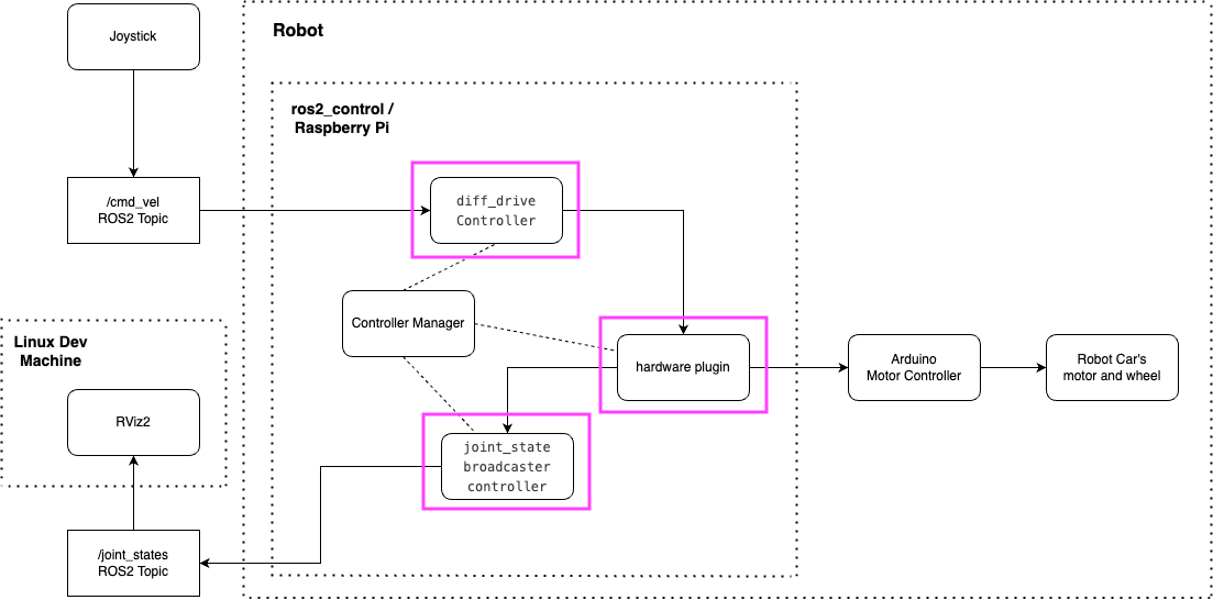
Recall from my blog “ROS 2 Control, Robot Control the Right Way” that I briefly touched on using motor encoders and ros2_control for a closed-loop robot system. In the following component diagram, the motor encoder contributes to the elements circled in red.
The Purpose of Motor Encoder in ROS
Odometry
In robotics, odometry (or odom for short) refers to the method of estimating a robot’s position and orientation over time based on sensor data from wheel encoders. In ROS, odometry is published as messages on the /odom topic. Specifically, encoders track how far each wheel has turned, and the ROS nodes utilize this data to estimate:
- Distance traveled
- Robot’s pose (position and orientation)
- Velocity
Feedback for Motor Control
The “diff_drive_controller” in ros2_control relies on encoder feedback for:
- Position control: Moving to a desired position.
- Velocity control: Maintaining a target speed.
The encoder data is part of the closed-loop system that adjusts motor commands in real time.
Joint State Publishing
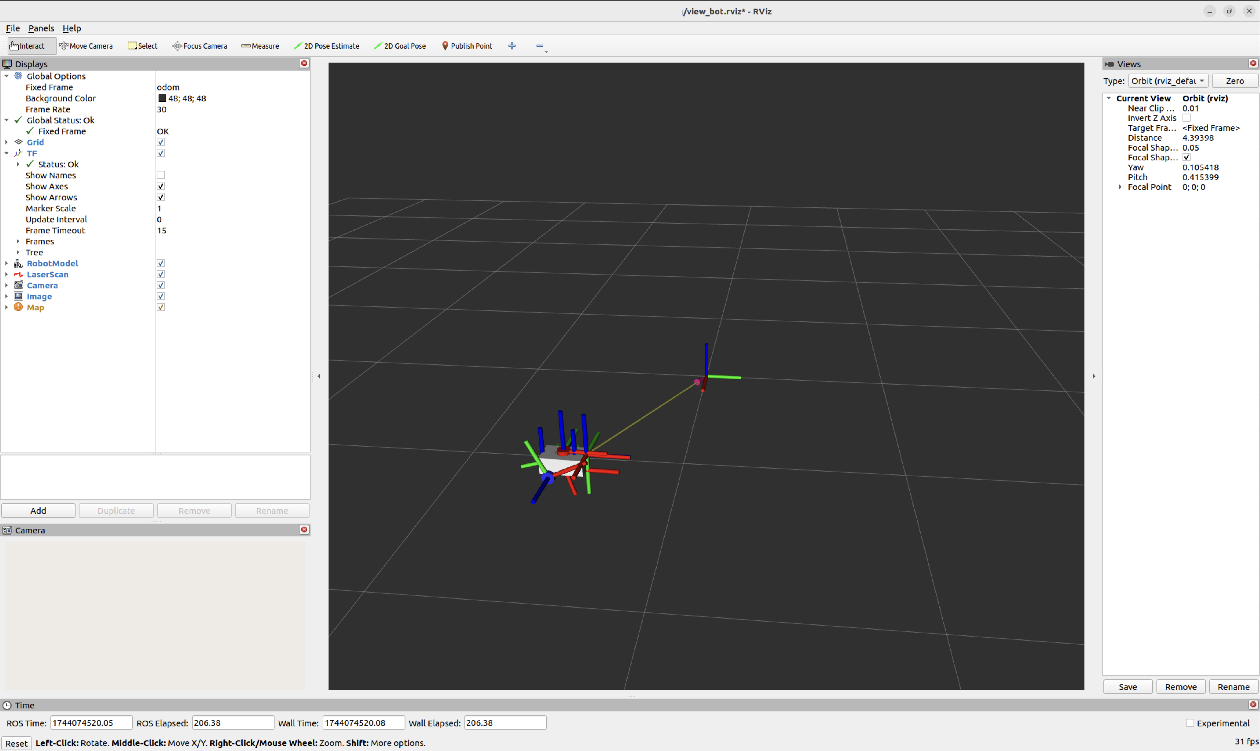
The readings from the encoders assist in reporting the position, angle, and velocity of the left and right wheel joints through the /joint_states topic, allowing users to visualize the robot in tools like RViz. This is how my robot appears in RViz.
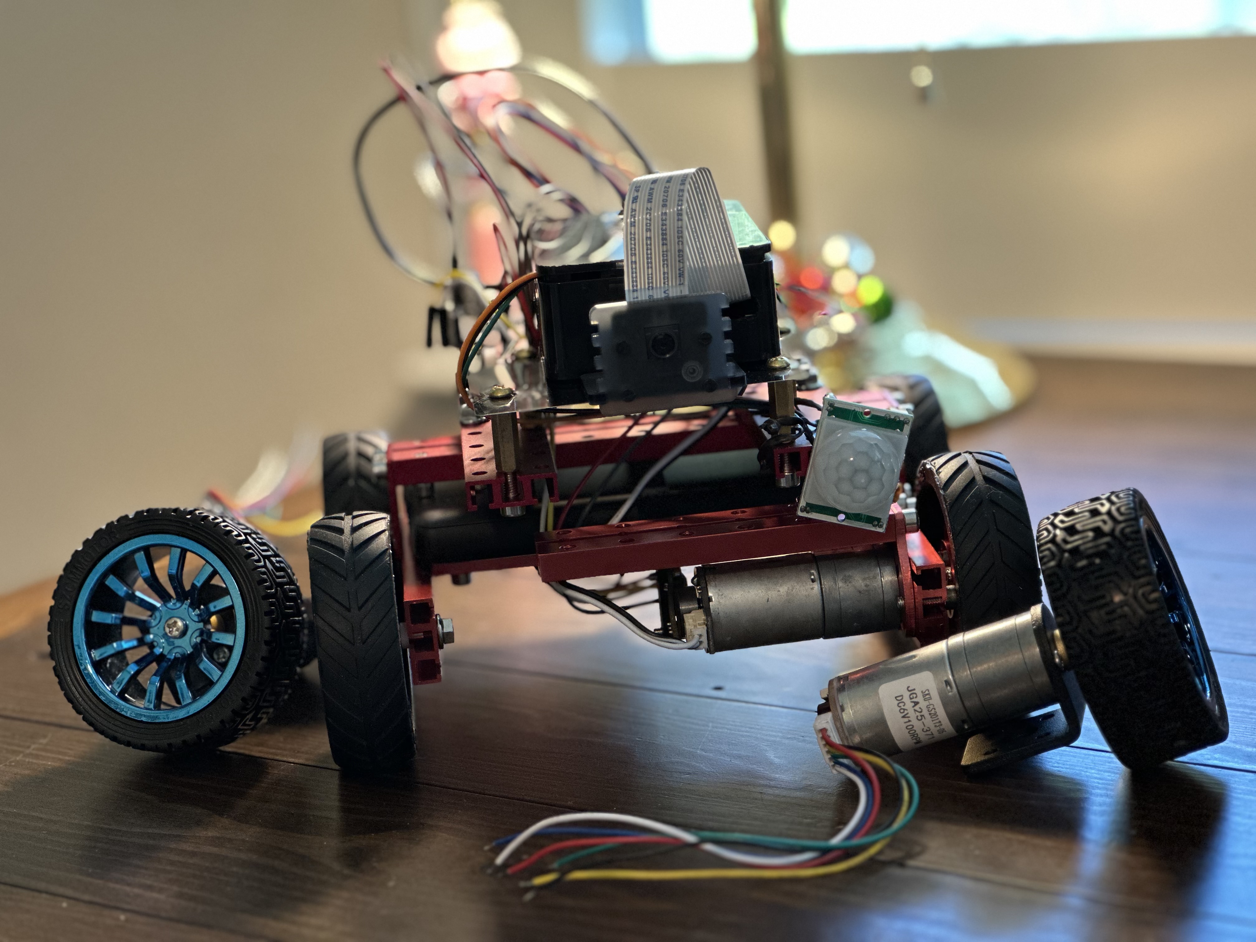
Upgrade DC Motors using Motor Encoders
I have several OSEPP DC motors that I used for different DIY robotics projects. These motors are high-quality, made from durable materials, and they provide high torque and a long motor shaft. They work well with the mechanical components of my robot.
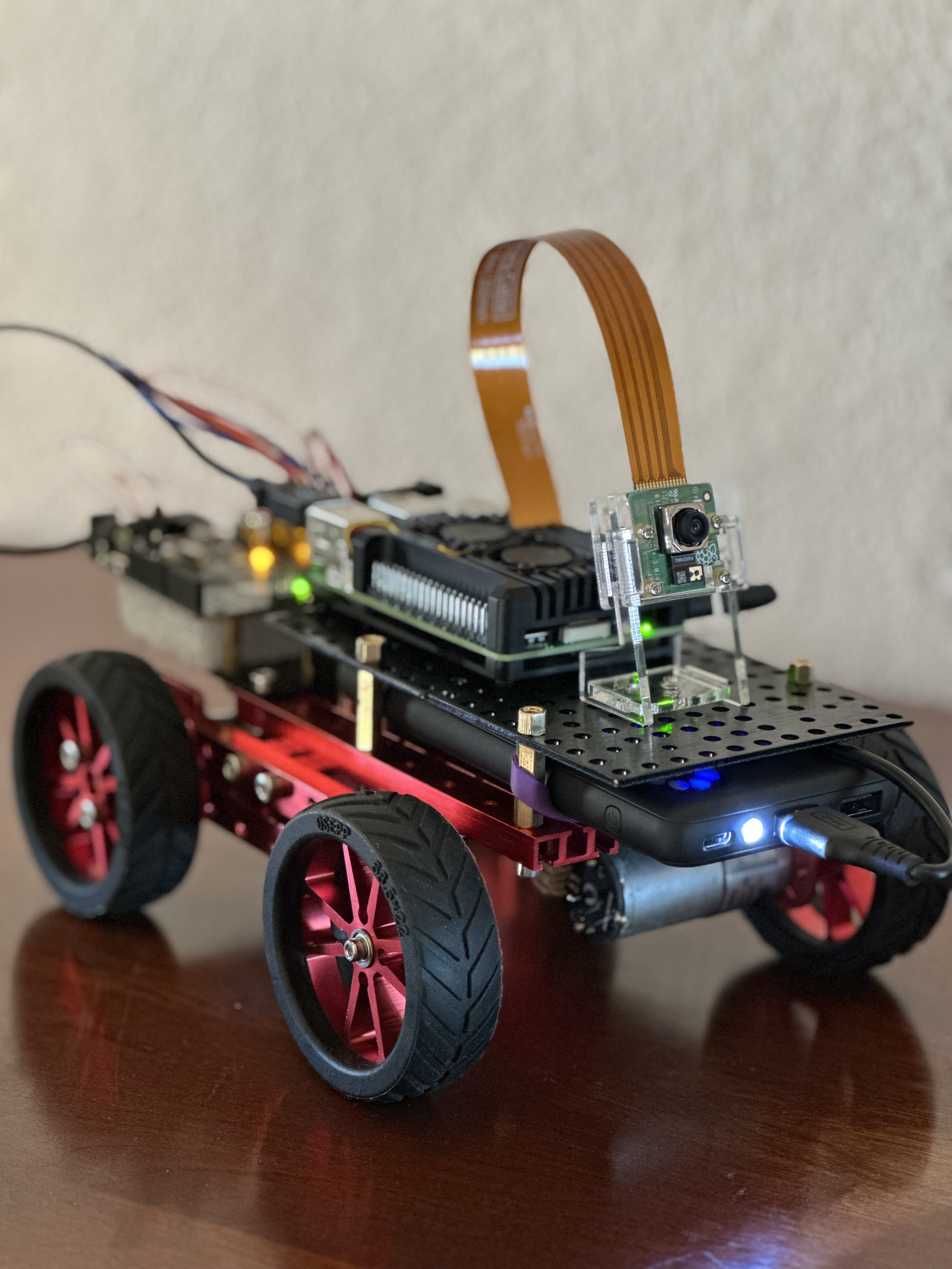
I considered using a new pair of DC motors with built-in encoders to simplify the setup. However, the ones I found on Amazon do not have a long enough motor shaft to work with my robotic parts.
After careful consideration, I chose to reuse my existing DC motors and enhance them with the OSEPP Motor Encoder. This motor encoder comes with a datasheet and detailed assembly instruction. Furthermore, I appreciate the build quality of OSEPP products.
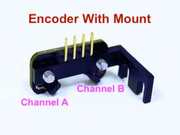
Quadrature Encoders
The OSEPP motor encoder is a quadrature encoder, a type of rotary encoder. It provides two output signals, Channel A and Channel B, that are 90° out of phase. This allows the system to determine:
- Speed (the rate at which the motor is rotating).
- Direction (If A leads B → clockwise. If B leads A → counterclockwise).
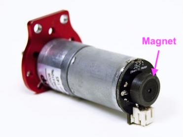
Test the Encoder Installation
After following the assembly instructions, I installed the encoder mount next to the motor’s magnet. I wired the encoders to the Arduino, and now it’s time to test the encoders’ readings.
I used the following Arduino program to check the readings.
#define ENCA A4 // Pin 2, A4
#define ENCB A5 // Pin 3, A5

void setup() {
  Serial.begin(9600);
  pinMode(ENCA,INPUT);
  pinMode(ENCB,INPUT);
}

void loop() {
  int a = digitalRead(ENCA);
  int b = digitalRead(ENCB);
  Serial.print(a*5);
  Serial.print(" ");
  Serial.print(b*5);
  Serial.println();
}
If everything is installed and wired correctly, we should see “value A” and “value B” interlacing in the Serial Plotter when I manually rotate the wheel.
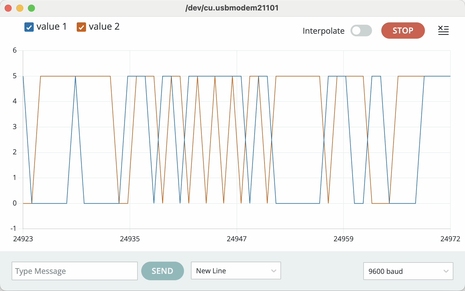
If the plot appears as a flat line or shows only one value oscillating while rotating the wheel, the issue may be related to the wire connection or the positioning of the encoder.
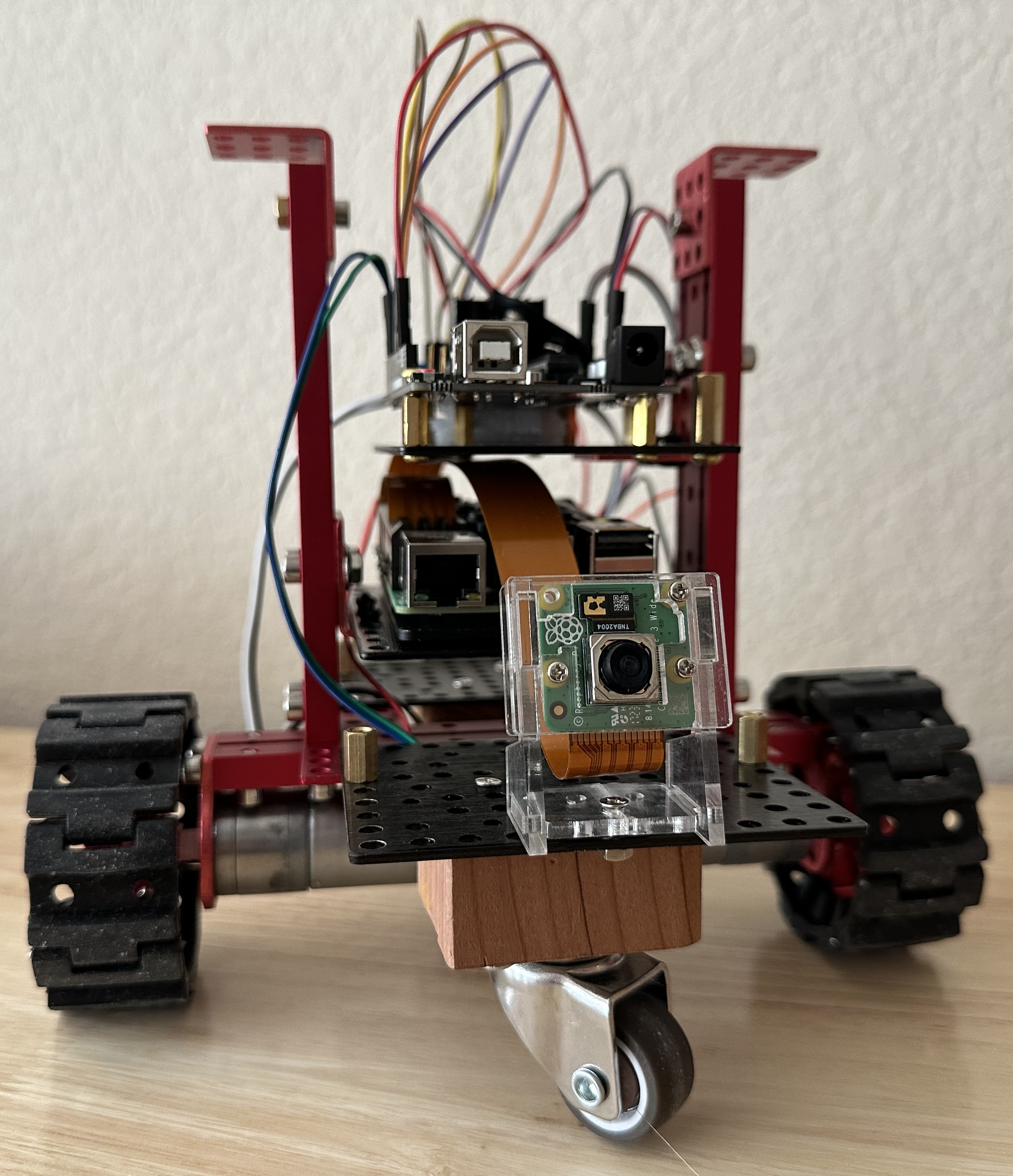
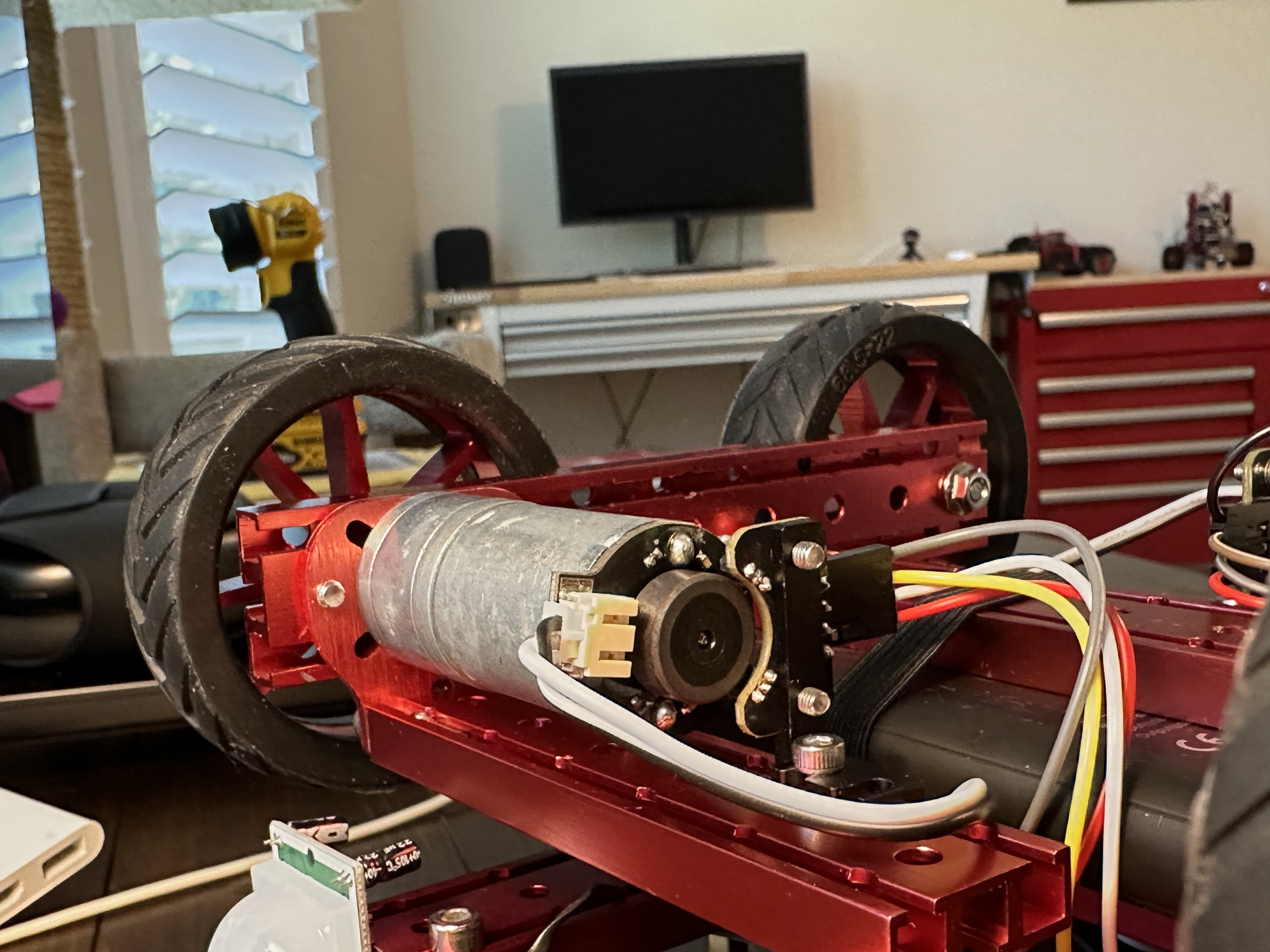
In my case, the problem was that the encoder mount was too far from the magnet. Additionally, the two channels were angled relative to the magnet. The A3144 sensor’s Channels A and B must be close to and parallel to the magnet’s side to detect the magnetic field while the motor shaft spins. Here is a picture of a properly installed motor encoder mount.
Encoder Count Per Revolution
To use the encoder in ROS2 Control, an important parameter is enc_counts_per_rev, which refers to the encoder counts generated for one full revolution of the wheel or motor shaft.
This parameter is defined in “ros2_control.xacro” and is used in the “read” and “write” functions of the hardware interface “DiffDriveArduinoHardware” to calculate the velocity command sent to the motor, as well as to compute the robot’s current pose and velocity.
Here is the “ros2_control.xacro”:
<?xml version="1.0"?>
<robot xmlns:xacro="http://www.ros.org/wiki/xacro">
    <ros2_control name="RealRobot" type="system">
        <hardware>
            <plugin>diffdrive_arduino/DiffDriveArduinoHardware</plugin>
			...
            <param name="enc_counts_per_rev">2000</param>
        </hardware>
Compute the enc_counts_per_rev
To determine the enc_counts_per_rev, I wrote an Arduino program that outputs the count after I manually rotate the motor shaft for one full revolution. I perform this rotation several times and calculate the average count, which gives me the enc_counts_per_rev of the motor.
#define ENC_A 2  // Encoder Channel A (Digital Pin 2)
#define ENC_B 3  // Encoder Channel B (Digital Pin 3)

volatile int pulseCount = 0;
bool counting = false;

void encoderISR() {
    if (counting) {
        pulseCount++;  // Increment count on each rising edge
    }
}

void setup() {
    Serial.begin(9600);
    pinMode(ENC_A, INPUT_PULLUP);
    pinMode(ENC_B, INPUT_PULLUP);

    // Attach interrupt for counting pulses
    attachInterrupt(digitalPinToInterrupt(ENC_A), encoderISR, RISING);

    Serial.println("Rotate the motor one full revolution and press ENTER.");
}

void loop() {
    if (Serial.available()) {
        Serial.read();  // Clear serial buffer

        pulseCount = 0;  // Reset pulse count
        counting = true;
        Serial.println("Start rotating the motor one full revolution...");

        delay(5000);  // Wait 5 seconds for manual rotation

        counting = false;
        Serial.print("Total pulses counted: ");
        Serial.println(pulseCount);

        Serial.print("Estimated CPR: ");
        Serial.println(pulseCount * 4);  // Multiply by 4 for quadrature encoders
        Serial.println("Press ENTER and rotate again.");
    }
}
Let robot dance in RViz
As mentioned earlier, one application of motor encoders is to help users visualize the robot using tools like RViz. Therefore, I created this robot dance clip. Cheers! :D
# start the robot on Raspberry Pi
ros2 launch my_bot robot.launch.py

# view the robot in rviz on the linux dev machine
rviz2 -d ~/dev/dev_ws/src/my_bot/config/view_bot.rviz