Simplify Robot Cars using TB6612 Motor Shield
Recall from my blog “ROS 2 Control, Robot Control the Right Way” that my robot uses an Arduino microcontroller. The Arduino cannot directly drive the motors because they require much more current than the Arduino can supply. Additionally, when the motors are turned off, they produce high voltages that could potentially damage the microcontroller pins. Therefore, the Arduino employs a DC motor driver to control the motors’ speed and direction.
Motor Driver
I select motor drivers based on the motor’s specifications, particularly its rated voltage and current. Additionally, I also consider the motor driver’s size and mounting methods. If I build a tiny robot, I must use a tiny motor driver.
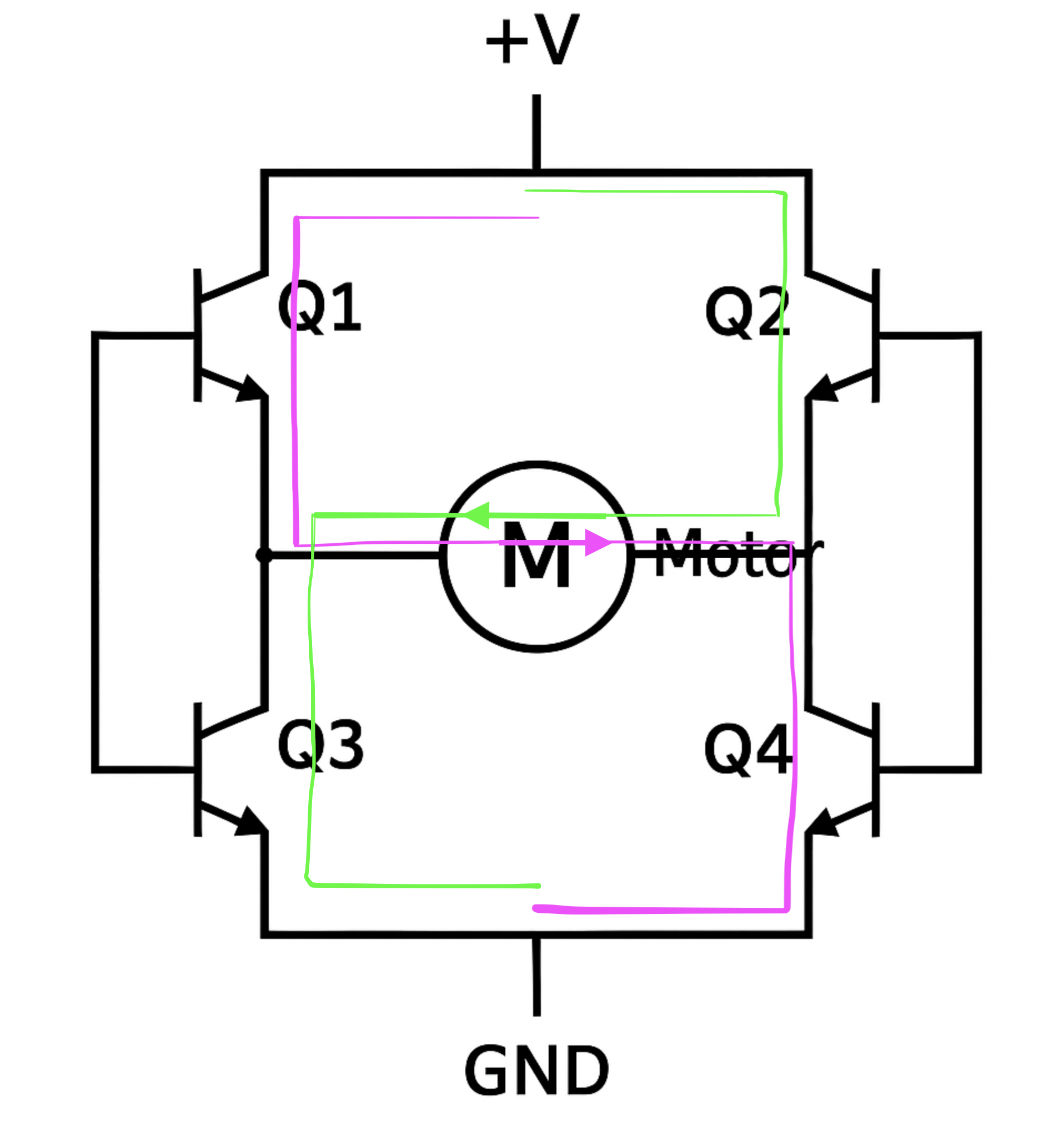
To control the motor’s direction, we commonly use a design called an “H-Bridge”, which consists of four switches (typically transistors) arranged in an “H” pattern, with the motor connected between the center points of the left and right legs. By turning on specific pairs of switches, current flows through the motor in one direction or the other, allowing it to spin forward or backward.
To control motor speed, we use PWM (Pulse Width Modulation) on the motor driver’s PWM input pin. PWM works by rapidly switching the motor’s power on and off and adjusting the duty cycle — the percentage of time the signal is HIGH versus LOW. A higher duty cycle (e.g., 80%) means the motor receives more power and spins faster, while a lower duty cycle (e.g., 30%) slows it down. In Arduino, this is done using the analogWrite function, where the value ranges from 0 (off) to 255 (full speed).
Examples of H-Bridge Motor Drivers. All of them have two channels for controlling two DC motors.
- L298N: supports motor voltage 5V - 35V and continuous current up to 2A.
- TB6612FNG: a tiny module. It supports motor voltage 4.5V - 13.5V and continuous current up to 1.2A.
- MX1508: an ideal choice for tiny motors. It supports motor voltage 2V - 10V and continuous current up to 1.5A.
L298N Dual H-Bridge
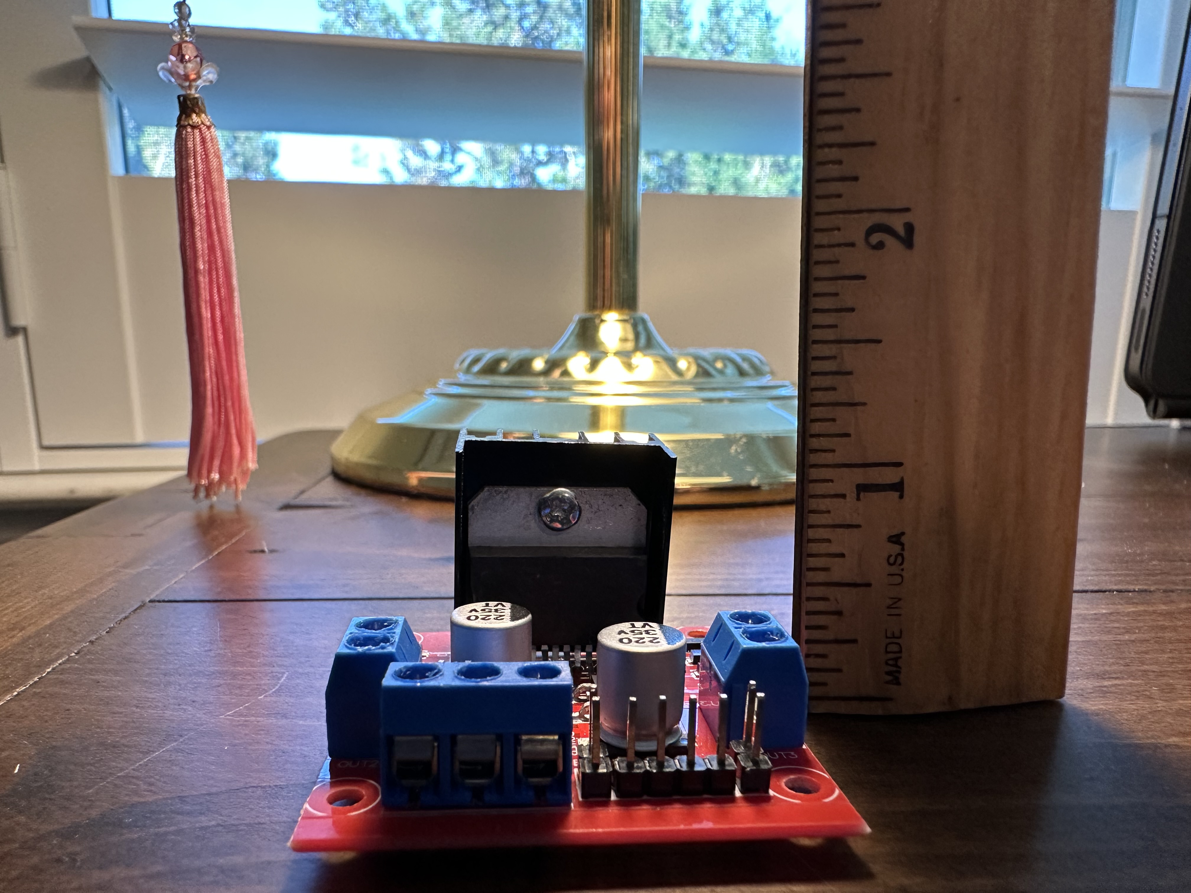
The L298N is a popular dual H-bridge motor driver that can control the speed and direction of two DC motors. It operates at voltages up to 35V and can handle up to 2A per channel, making it suitable for small to medium-sized motor control applications. It is very affordable, widely available, and easy to use.
The L298N uses bipolar junction transistors (BJTs) in its H-bridge design, which are less efficient than MOSFETs, resulting in more heat and significant voltage drop. Typically, a single bipolar transistor experiences a drop of approximately 0.7 volts. When two transistors are employed simultaneously in an H-Bridge configuration, the total drop is estimated to be around 1.4 volts. Consequently, if a 9-volt supply is applied to the H-Bridge, the motor will actually receive only 7.6 volts.
Another problem I face when using the L298N is that it is bulky and requires messy wiring to connect the necessary L298N pins to the Arduino. Here are the pins that must be connected:
- EnableA, EnableB (connect to Arduino’s PWM pins to control the motor’s speed)
- IN1, IN2, IN3, IN4 (control the motor direction)
- 5V logic voltage, GND
TB6612FNG Dual H-Bridge
The voltage drop, heat generation, and bulky size led me to explore other Dural H-Bridge motor drivers.
TB6612FNG features a newer, more efficient design, utilizing MOSFETs for switching, which results in a lower voltage drop and higher efficiency. Overall, TB6612FNG is smaller, cooler, and more efficient, making it a better choice for most projects unless higher voltage tolerance is needed from L298N.
Regarding the wiring, TB6612FNG uses the same pins as L298N and can serve as a drop-in replacement for L298N.
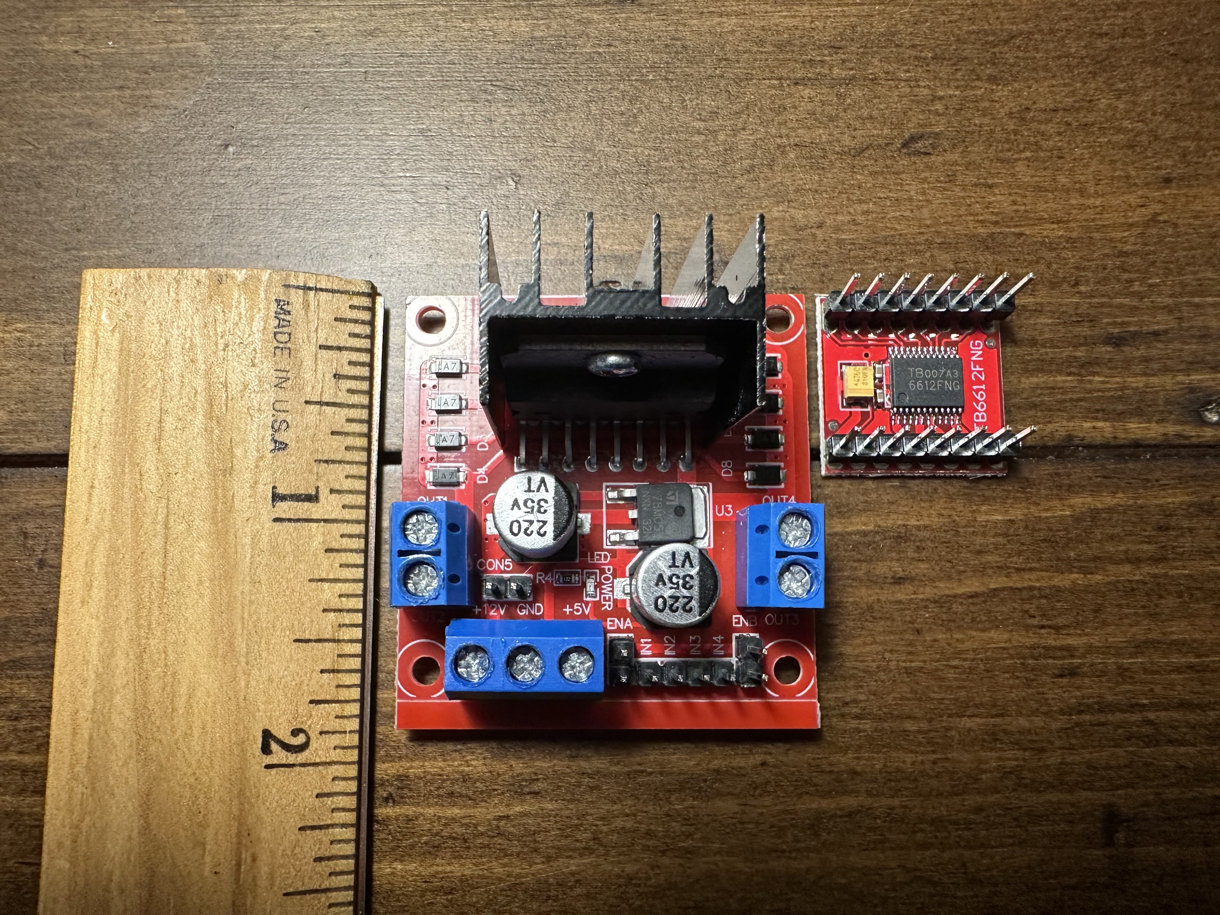
Here are L298N and TB6612FNG side by side; TB6612FNG is less than one-fifth the size of L298N.
Motor Shield
An Arduino Motor Shield is an add-on board (or “shield”) that plugs directly onto an Arduino to make it easy to control DC motors, stepper motors, and servos. It contains motor driver chips, such as the L298N or TB6612FNG, that handle the high current and voltage required by motors, which the Arduino alone cannot supply.
The shield simplifies wiring and programming by using a standard pin layout, and many shields come with Arduino libraries to make coding easier.
Meet the OSEPP TB6612 Motor Shield
The OSEPP TB6612 Motor Shield uses two TB6612FNG dual H-bridge driver chips, allowing independent control of up to four DC motors (M1–M4). All pins from the shield are already connected to the Arduino once the shield is stacked onto the Arduino board, removing eight wires from the configuration.
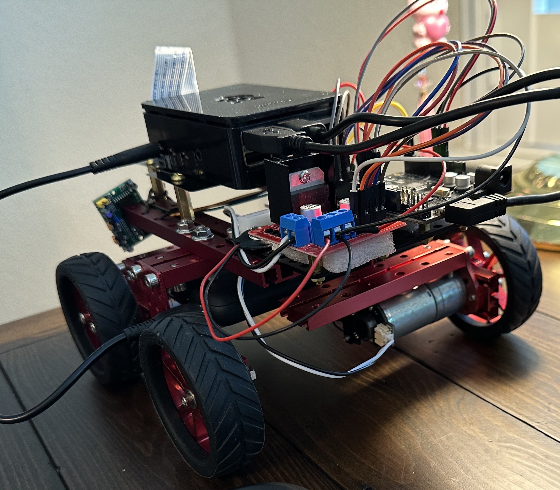
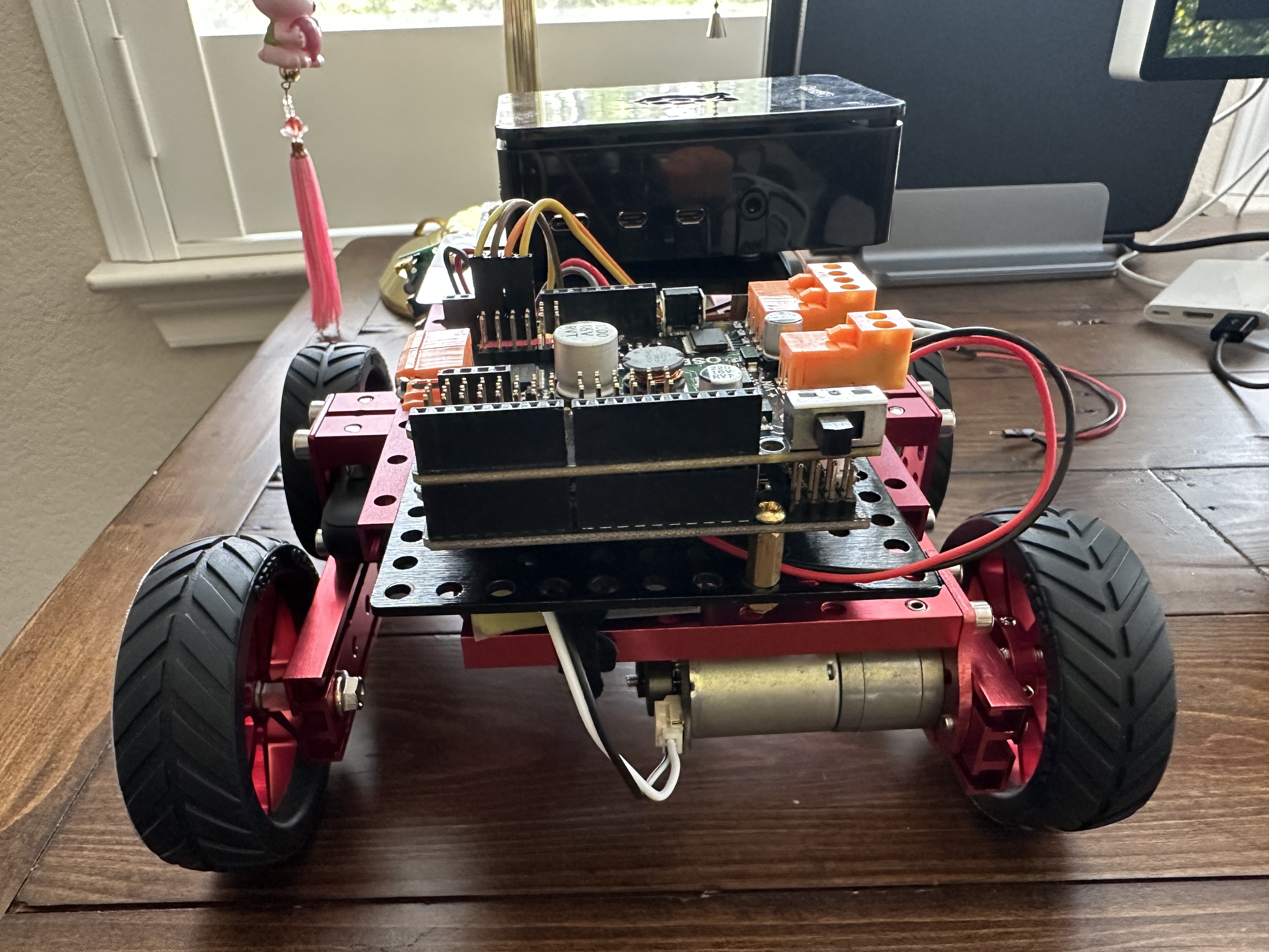
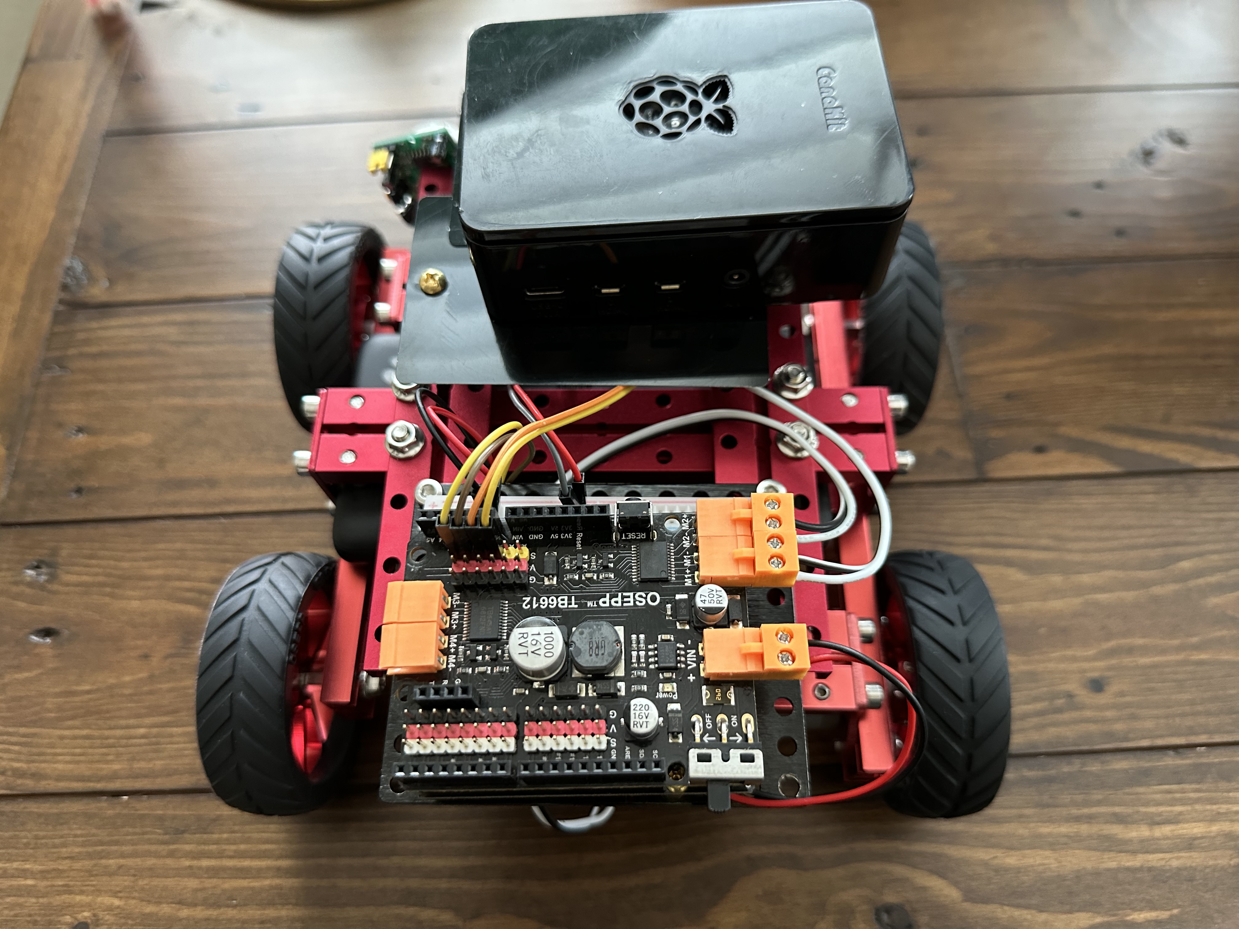
Here are the pictures of the updated wiring. I replaced the L298N motor driver with the TB6612 motor shield. Once I connect the motors to the motor shield using the wire clips, I don’t need any additional wires to control the motor. The four wires on the motor shield are for the motor encoders, not for the motors themselves.
The motor shield has convenient “V” and “G” rails to provide the 5V Logic Voltage and GND for the encoders and sensors. However, they are NOT directly connected to Arduino’s 5V/GND rails, so be careful when using them. More details will be discussed in the next section on how to use them correctly.
Troubleshooting Lessons, Common Pitfalls
Once the wires are cleaned up, the next step is to update the code to make it work again. I struggled with that for a couple of days, and here are some crucial details I learned about using the TB6612 Motor Shield.
Dedicated Arduino Digital Pins
Unlike a standalone motor driver, the OSEPP TB6612 motor shield has a Driver Schematic, which indicates that each H-bridge connects to dedicated Arduino digital pins for direction and PWM control, with motor power supplied through a VIN terminal and routed internally to the driver chips’ VM pins. This means I need to update the Arduino sketch to use those specific pins for motor direction and PWM control.
The STBY (standby) pins are internally connected to 5V, keeping both motor drivers active by default. This design integrates neatly with Arduino UNO headers, requiring no external wiring for basic motor control.
Each type of shield has its schematic. Grok or ChatGPT are currently not aware of it and hallucinate heavily. For example, they believe the reason the code is not working with the TB6612 motor shield is that the STBY pin is not set to HIGH and insist I run a jumper wire to connect pin 10 to 5V since pin 10 is usually the STBY pin. :D
PWM with One DIRECTION Input
From the OSEPP example code, I learned that I only use one pin to control the direction, unlike L298N or TB6612FNG, which use two input pins for the direction. Therefore, to stop the motor, I must set PWM to 0 rather than setting the input pins to LOW.
Here is the Arduino sketch I created to test the DC motor with the OSEPP TB6612 Motor Shield:
// Motor M1 (Motor A)
int enA = 11;    // PWM speed control
int dirA = 8;     // DIRECTION control

// Motor M2 (Motor B)
int enB = 3;     // PWM speed control
int dirB = 12;    // DIRECTION control

void setup()
{
  // Set all the motor control pins to outputs
  pinMode(enA, OUTPUT);
  pinMode(enB, OUTPUT);
  pinMode(dirA, OUTPUT);
  pinMode(dirB, OUTPUT);

  Serial.begin(9600);
}

// Run the motors in both directions at a fixed speed
void loop()
{
  // Run Motor M1 and M2 forward
  Serial.println("Forward");
  digitalWrite(dirA, HIGH);
  analogWrite(enA, 150); // speed 0–255

  digitalWrite(dirB, HIGH);
  analogWrite(enB, 150); // speed 0–255
  delay(2000);

  // Reverse the motor directions
  Serial.println("Reverse");
  digitalWrite(dirA, LOW);
  digitalWrite(dirB, LOW);
  delay(2000);

  // Stop the motor
  Serial.println("Stop motors");
  analogWrite(enA, 0);
  analogWrite(enB, 0);
  delay(1000);
}
0 Volts at M1, M2?
OSEPP TB6612 Motor Shield has a toggle switch. Even if the shield’s VIN terminal is connected to a battery and the shield is powered, the motors are NOT powered until the shield’s switch is turned on. I was stuck on this and could not figure out why the motor did not spin until I noticed the switch on the shield.
The Power Puzzle: VIN, VM, and the “V” and “G” Rails
The motor shield includes logic rails labeled “V” and GND rails labeled “G” for powering encoders or sensors and exposes signal pins alongside them for convenient 3-pin connections. However, the pins on those rails are not directly connected to Arduino’s 5V/GND rails. They are only powered when the shield’s VIN terminal is connected to the battery and the motor shield switch is turned on. Otherwise, the encoder signal lines become “floating” and produce oscillating HIGH/LOWs.
The alternative is to use Arduino 5V and GND for a clean and stable reference voltage, which is what I ended up choosing in my setup.
Update to the ROS Arduino Bridge Sketch
I updated the ros_arduino_bridge repository to support the TB6612 motor shield and modified the encoder_driver to use analog pins A2-A5 for encoder readings. This repository serves as the hardware interface for the ros2_control of my robot car.
Cheers!